
Figure 1: CFD simulation of ECN’s GDI fuel Injectors using GridPro grids.
1988 words/ About 10 mins
In Search of “The Ideal Car”!
Driven by the need for cleaner, environment-friendly vehicles to abide by stricter government regulations, it is imperative for automakers worldwide to make cars more fuel-efficient and less polluting. Auto companies are forced to embrace the concept of “downsizing” – building increasingly small, compact, yet powerful engines. Downsizing, along with other technologies like turbocharging and gasoline direct injection (GDI) has the potential to bring down fuel consumption and carbon dioxide emission by at least 15 percent.
Lately, auto researchers have narrowed down on gasoline direct injection (GDI) systems to meet the expectation of economical fuel consumption and lower emissions.

Figure 2: GDI fuel injectors with varying holes. Image courtesy NOSTRUM energy.
History
GDI is not a new invention. It made its first appearance way back in 1925 for the first time in a Hesselman airplane engine. Mercedes Benz was the first auto manufacturer to incorporate them in their cars during the early 1950s. However, as the port fuel injection (PFI) system gained popularity, GDI rapidly faded away. Only very recently, a decade ago, its importance was rediscovered and has become the new trend among automakers worldwide.
For the past 5 years, it has been the standard feature in many European vehicles, from small vehicles to highly-efficient sedans to premium luxury and sports cars. It is estimated that, by 2020, nearly 25 percent of all vehicles in the world will be equipped with a GDI system.
What Makes GDI Stand Apart from Conventional PFI?
Unlike in PFI, the gasoline in the GDI system is injected directly into the combustion chamber in the form of a finely atomized spray at a very high pressure of over 200 bars. These extremely small droplets help to achieve good contact with the oxygen in the air, causing virtually all fuel to get burnt up instantaneously on ignition. This results in achieving a higher compression ratio (in other words greater efficiency) and lesser particulate matter generation.
Direct injection greatly contributes to cylinder cooling. Simultaneous partial opening of the intake and exhaust valves causes the fresh intake air to push the hot exhaust air out of the cylinder. Supplementing this cooling effect, the direct injection of the fuel cools the combustion chamber further, resulting in achieving higher compression and knock threshold. The finely atomized state of the injected fuel prevents fuel droplet deposition on the chamber walls, resulting in more cleaner and efficient combustion.
Drivers will be perceiving this betterment in the form of increased torque, improved driving dynamics, and reduced fuel consumption. Progress in GDI technology is at an advanced state with injectors from companies like Bosch, Continental, Delphi, Denso, etc, designing for worldwide use for different fuel qualities.
Challenges in GDI research
Technology has taken giant strides in the last 10 years in making GDI technology better and more efficient, however, there is still a large scope for further improvement. Not everything is understood and decoded as to what actually happens inside the GDI-based combustion process, eluding the goal of achieving complete control over the successive events inside the combustion chamber. This is mainly because there are way too many variables influencing the chain of complex activities, which eventually lead to energy conversion in an engine.
Challenges come in the form of drilling self-similar, smooth-walled injector holes whose diameters are as small as 0.25 to 0.1 millimeters. Additionally, the high injection pressure triggers turbulent flows, which often show asymmetric behavior and hole-to-hole variation while leaving the nozzle. Further, the phase changes the liquid fuel undergone due to cavitation, flash boiling, and evaporation add to the complexity.
Though some of these complex physics is already researched and understood in the direct injection diesel engines, it is the added factor of phase change through flash-boiling which makes GDI research even more challenging. Presently, researchers world over are investing all their efforts in understanding the link between internal nozzle flow with atomizing, vaporizing, and flash boiling of sprays.
Video 1: Showing the Experimentally observed flashing (left) and non-flashing (right) GDI injectors sprays. Under flashing conditions, uniform contact of fuel is observed, while under non-flashing conditions, non-uniform contact of fuel is observed with gaps allowing ingestion of ambient gas.
CFD Going Hand-in-Hand with Experiments in Understanding GDI Sprays
Researchers rely on both experiments and CFD to get a better insight into the complex flows in GDI based combustion process. Being complementary to each other, they have been very useful in understanding GDI better.
Lately, CFD has stepped in to fill the void left by the limitation in experiments. Many experiments rely on semi-empirical zero or 1D models to describe their observations. Though beneficial to some extent, they fall short of representing the spray fields generated by complex fuel injectors. Limitations in experiments get exposed in cases where they fail to capture the influence of subtle differences in GDI sprays from nominally identical injectors, fabricated by different techniques.
This underscores the importance of CFD as a design tool as well as a research tool in understanding the complex physics associated with these spray systems.
At the same time, experiments help in validating and verifying the CFD results. Researchers crosscheck their CFD results with experimental images for qualitative agreement, and for checking flow parameters like rate of injection, they fall back on the raw experimental data for quantitative verification.
Video 2: CFD simulation of flashing (left) and non-flashing (right) GDI fuel injectors sprays. Under flashing conditions, uniform contact of fuel is observed, while under non-flashing conditions, non-uniform contact of fuel is observed with gaps allowing ingestion of ambient gas. video source: E. T Baldwin et al (1).
What Does CFD Brings to the Table?
Not all the data required for GDI injector designs can be obtained by experiments alone. CFD has got a lot to offer in understanding the flow physics and in optimizing the design. Unlike experiments, the physical small dimensions of fuel injectors are not an issue, and their ability to completely capture the internal flow and external spray in one single simulation makes them the front-runner tool in GDI research. Also, CFD provides extensive details of the internal nozzle flow and its influence on the spray. Another major setback of experiments is that they are way too expensive. CFD on the other hand is cheap, reliable, and less time-consuming.
CFD is been extensively used in understanding spray flow turbulence, the influence of nozzle geometry, aerodynamic instabilities on GDI sprays the influence of transient needle motion on internal nozzle flow and near field sprays, etc.
Most researchers working in the field of fuel injectors rely on the vast database of Engine Combustion Network (ECN). This is an international collaboration among CFD and experimental researchers in engine combustion, engulfing auto industry, research labs, and universities from around the world, working in tandem with the objective of standardizing and validating the best practices for numerical and experimental studies in the field of internal combustion engines using gasoline and diesel fuels.
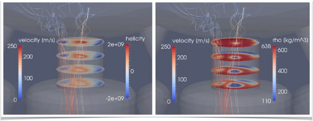
Figure 3: Image taken midway through non-flashing simulation shows, two counter-rotating vortices being directed into a nozzle passage. Image source: E. T Baldwin et al (1).
Recent research work in the field has shown that the flow inside GDI systems is quite complex and susceptible to variation by factors previously unknown. For example, it is observed that counterbore experiences a pressure depression, which triggers further expansion of fuel vapor. Another study noticed that the nozzle asymmetry induces hole-to-hole variation in mass flow rate and the needle lift significantly affects the flow patterns. Interestingly, because of the minuteness of the holes and various parts of the GDI spray system, even a subtle change in the manufacturing imperfections such as corner radius, hole, and counterbore length, diameter, convergence/divergence angles, results in noticeable changes in hole-to-hole mass flow rate and density profiles.
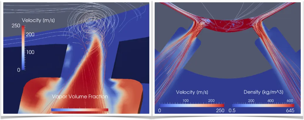
Figure 4: String flash boiling causing swirling flow in the sac (left image) and spray angle expansion (right image). Image source: E. T Baldwin et al (1).
For internal combustion engine applications, cavitation and flash boiling are two common phase-changing phenomena in fuel injection systems. In these applications, when the local pressure drops below the saturation pressure of the fuel, liquid fuel gets transformed to vapor, which has a huge influence on spray formation and atomization. While the thermodynamic phenomenon of cavitation is prevalent in high-pressure diesel injectors, flash boiling is generally observed in GDIs.
In the recent work of E. T Baldwin et al, CFD has precisely captured the highly complex internal injector flow with many transient and interacting vortices.
Further, the simulation reveals that the vortices induce flash boiling, perturbations in spray angle and direction, and fluctuations in mass flux. The resultant swirling spray contains a thermal non-equilibrium vapor, ultimately reducing the average flow density.
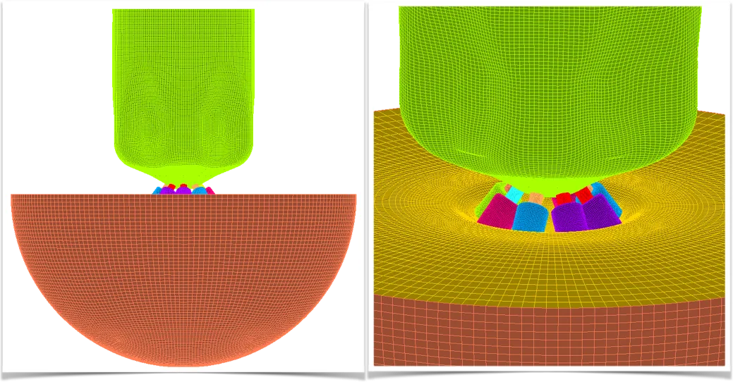 Figure 5: Computation domain with the structured multi-block grid using GridPro.
Why Multi-Block, Why not Others?
The meshing requirements of these tiny yet complex configurations are quite unique and challenging. The configuration demands a fine mesh with sizes going down to a few microns, to resolve the geometry and the associated flow physics. Researchers usually make use of Cartesian and Structured multi-block grids to discretize the flow domain. While Cartesian grids help in quickly generating unit aspect ratio mesh in no time, structured grids come in handy in generating optimized high aspect ratio grids.
One of the gridding challenges posed by the geometry is the variation in flow passage because of needle movement. As the needle moves in the sack, the passage can become as small as 5 microns. Structured multi-block allows accurate capturing of this narrow passage by placing high aspect ratio hex cells and at the same time showing flexibility to fill the excess space as the needle moves away, without increasing the total cell count. Without anisotropic refinement, the cell count would easily reach 18 million against 1.4 million in structured Multi-Block, with most of the cells being placed within the 5-micrometer narrow channel.
Simulations for such GDI nozzles are computationally expensive. One transient URANS simulation on a 1.4 million grid will take around 3500 CPU hours i.e. 36-48 hours on a 96 core machine. As a consequence, researchers are constantly looking to reduce the cell count to as minimal as possible. In this aspect, structured grid scores over Cartesian’s trim approach. E. T Baldwin et al used GridPro to generate a 1.44 million structured multi-block grid with a minimum cell size of 7 microns.
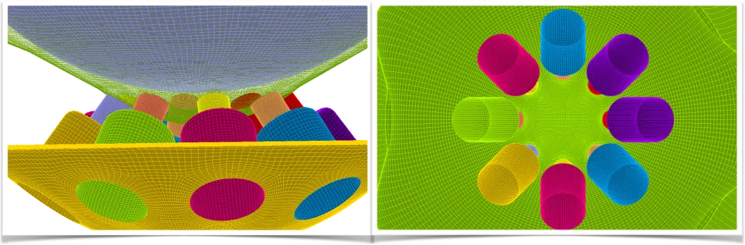
Figure 6: High-quality, smooth meshes in and around the nozzle holes.
Also with structured grids, grid-uniformity among the 8 holes is strictly maintained, while it is not possible in a Cartesian or Unstructured gridding framework. With manufacturing imperfections bringing a hole-hole variation in physics, gridding variation will further increase the uncertainty in the simulated data. The innate nature of multi-block-based meshing alleviates this problem to a large extent.
GridPro with scripting capability comes in as a powerful handy tool in generating optimal grids in an automated environment. One topology (Blocking) is all that is required for varying needle position and even nozzle diameter variations. Smoothing algorithms optimize the grid points to fill in the ever-changing domain.
Video 3: Shows the grid movements as the needle lifts and wobbles.
Concluding Remarks
CFD research on GDI injectors helps in getting a better understanding of the combustion process and in turn, helps in achieving more control over the combustion process, which outwardly manifests as increased fuel economy. Technologies come and go, but it looks like GDI is here to stay. Though this technology has made amazing progress since its inception, there is still scope for further progress and improvements. CFD will continue to play a pivotal role in designing cleaner and more fuel-efficient engines.
Further Reading
Reference
1. “String flash-boiling in gasoline direct injection simulations with transient needle motion”, E.T. Baldwin, R.O. Grover Jr, et al, International Journal of Multiphase Flow,87, 2016, 90-101.
2. “Modeling of Internal and Near-Nozzle Flow for a Gasoline Direct Injection Fuel Injector”, Kaushik Saha, et al, Journal of Energy Resources Technology, Sept 2016, Vol. 138.
3. “CFD optimisation for GDI spray model tuning and enhancement of engine performance”, Michela Costa, et al, Advances in Engineering Software, 49, 2012, 43-53.
Wow, this article really shed light on how crucial CFD is for designing fuel injectors efficiently! Understanding fluid dynamics seems like the key to optimizing performance and fuel efficiency in engines. It’s fascinating to see how technology like this can make such a big difference. Great read!