
Figure 1: Parametric variation of impeller blades for CFD-based shape optimization. Image courtesy – Caeses.
2342 words / 12 minutes read
Introduction
Optimization is in our genes. Knowingly or unknowingly we use it in our day-to-day decision-making process. Whether it is deciding on which television set to buy, planning for a trip, hosting a small birthday party, we use optimization. We may not use fancy gadgets or software to do so, but still, we go about doing it in our minds or on a piece of paper. Odd as it may sound, this is no different from designing an aircraft or designing a fuel-efficient car, or designing a house with proper sunlight and ventilation. The magnitude, tools used, timescales, human effort/planning involved, level of complexity, etc, may differ, but nonetheless, at the core, it is just the same – optimizing to find a good, possibly the best solution under the given circumstances. In technical jargon, it means minimizing or maximizing one or multiple objectives within known constraints.
The application of optimization covers the length and breadth of science and engineering. From economics and finance to molecular modeling, to bio-medical, geophysics. The field is vast and will rightfully need a textbook to cover the length and breadth of the field. In this article, we restrict ourselves to presenting an overview of one small segment in optimization, namely, shape-optimization.

Shape Optimization
Shape optimization deals with finding the right shape or contour for an engineering component/product within certain constraints, by modifying a set of predetermined boundaries. In a product-design environment, they are pretty handy. They help in getting a better understanding of the design space and also provide guidance to the design team in creating products with superior performance at lower risks. Further, they aid in cutting down the time involved to transfer a product from ‘design table to users table’. Lastly, optimization saves costs by avoiding expensive last-minute modifications.
Shape optimization can play a crucial role, both in the early and advanced phases of a design cycle. In the early phase, they aid to explore newer ideas and possibilities and in advanced stages of product design, their flexible and rapid responsive abilities help to make last-minute design changes. The repercussion of all these positives is that it not only helps to create products of superior performance but also expands the range of design variants to choose from. In addition, they tremendously expand the knowledge base for making high-quality decisions.
Shape Optimization Approaches
When we talk about shape-optimization, there are various methods and approaches, and we can broadly classify them as parameter-based and parameter-free techniques.
The parameter-based approach is based on the philosophy that, any product/geometry in all its complexity and details can easily be described by a bunch of parameters. Here, every feature, every contour is defined by a set of parameters, and at any point in time, their values can be modified to bring in a corresponding change in shape.
Various shape optimization techniques have been in usage in the design industry for many decades and by far, parameter-based optimization is the most popular among all. The reason is, in this approach, designers can intuitively understand and appreciate each parameter, and also it is easy to co-relate how a change in a parameter’s value impacts the design objectives. More importantly, this approach is most amenable for conducting multi-objective and multi-disciplinary optimizations without any conceptual barriers.
One subtle thing which needs to be appreciated about parametric modeling for CFD is that not all parametric models built by traditional CAD systems are ‘CFD ready’. Loaded with all the intricate details of the product, these parametric models are good for production or manufacturing purposes, but not for CFD simulation. What is ideally needed for a CFD-based optimization cycle, is a CAD system that defines the fluid-wetted geometries with a few significant parameters, deliberately dropping off characteristics of lesser significance.
To specifically construct such CFD-friendly ‘engineering models’, a new breed of CAD called upfront CAD systems has come into existence. These new CAD systems like Caeses, PTC Creo, Autodesk, Ansys Spaceclaim are specifically designed to provide simulation-ready CAD models. Though each of these has many differences among themselves in what they offer for the CAE user, they are built to meet the requirements of both initial and advanced phases of product design.
Upfront CAD systems provide parametric models focusing on the engineering design cycle rather than production. Depending on how the geometries are built and tweaked to get a new shape, parametric modeling can be further classified into partially-parametric and fully-parametric models. In the former approach, parameters are defined to bring in a change in an already existing geometric object, while in the latter, the geometry is built right from scratch and one can mess with the parameters to induce a shape change in a multitude of ways.
Diagonally opposite to the parametric approach is the parameter-free approach to shape creation and modulation. This creative approach encompasses techniques in which the fluid flow itself defines the shape of the geometry, organically carving out the surface contours by taking inputs from the CFD simulation !!!
Video 1: Automated parametric variation of wing-geometry for CFD-based optimizations. Video courtesy – Caeses.
Fully-parametric modeling
Based on the extent of usage of parameters, parameter-based approaches are further differentiated into fully-parametric and partially-parametric methods. The fully-parametric technique is based on the thought process that, any shape is realizable from scratch and can be constructed by a set of parameters, amenable for change at any point in time, to create a new variant. Simple geometries can be built with basic parameters like length, breadth, height, radius, etc, while complex objects will need parameters derived from formulas and background computations.
Usually, all parameters are set relative to or in combinations to construct a hierarchical model. One can perceive this method as something which takes in a bunch of parameters as inputs and throws out a shape/geometry as an output. It is this aspect of fully-parametric modeling that makes it the ideal candidate for shape optimization, as it has the inherent elements to be flexible to bring in large changes in the early design phase and also make necessary micro-adjustments in the advanced stages of product design.
Partially-Parametric Modeling
In this approach, parameters are only defined to make changes on an already existing baseline geometry. Some of the popular techniques under this umbrella include – free-form deformation, morphing, and shift transformation.
Video 2: Application of free-form deformation for various parts of a car. Video courtesy – Sculptor.
In free-form deformation, a matrix of points called control points encloses the entire geometry or a specific region that needs to be reshaped. A correlation between these control points and the actual grid representing the surface is constructed. With this arrangement, any movement of the control point creates a corresponding deformation of the actual surface. Video 2 shows an example of free-form deformation in action. The technique is pretty powerful and can be applied to bring in changes in surfaces, volumes, and meshes too. Since the defined set of control points are usually in the shape of a box, the technique is also nicknamed box-deformation.


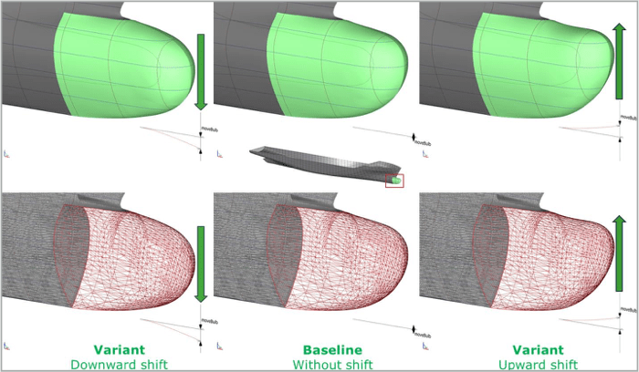
In the third popular partially-parametric approach of shift transformation, reshaping of the geometry is brought by providing a finite displacement to a surface point relative to its initial position in 3-dimensional space. The displacement can be enforced equally well on continuous data like surface patches, as well as on discrete data like points, tria-meshes. Figure 7, illustrates this technique by effectively changing a container ship’s bulbous bow.
In general, it is observed that partially-parametric approaches like free-form deformations, morphing, and shift-transformations are relatively quick and easy to set up when compared to fully-parametric techniques. They are well suited for fine-tuning without much overhead. However, since they have less knowledge about the baseline geometry, it is a bit difficult to come up with large shape modifications.
Parameter-free optimization strategies
Finally, the last group of techniques that we can talk about in shape optimization is parameter-free techniques. In this category, the CFD flow decides what the shape of the geometric surface should be. Two popular methods which have garnered industrial acceptance under this approach are topology optimization and adjoint simulation-based techniques.
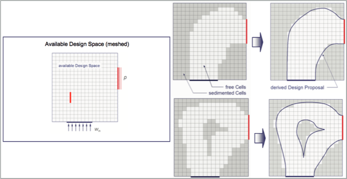
The topology optimization method is well suited for internal flow problems. The fluid flow itself tells how the flow domain should be to fulfill a set of design objectives. Figure 8 and 9, illustrates this approach graphically.
Consider a case where there are an inlet and an outlet placed at 90 degrees to each other and we need to construct a flow passage within the ‘available design space’. A CFD mesh is generated to fill the domain and for the set of boundary conditions, the CFD solver is run. Parallelly the topology-optimization algorithm is switched on, which exchanges data continuously with the CFD solver at each iteration. Both CFD simulation and optimization happen simultaneously and as a consequence, within one CFD solver run only, a shape optimized geometry can get created.

Video 3: CFD Topology optimization of a 90-degree elbow. Video courtesy Tosca.
Internally, what happens is that, based on a set of redesign rules laid by the Engineer, say, reduction of recirculation zone, the optimization algorithm suppresses the flow on a cell by cell basis, while parallelly the CFD solver tries to iteratively converge its residues. This sedimentation of the design domain continues to happen, iteration after iteration until no more cell removal happens or constancy is achieved. This final shape organically carved by the fluid is extracted to get a CAD surface and a fresh CFD simulation is run to validate the outcome. Video 3, shows this optimization technique in action.
Video 4: Application of adjoint solver-based shape optimization technique for an exhaust pipe system with an objective to reduce pressure drop and increase flow uniformity. video courtesy – Ansys.
Likewise, the adjoint-based optimization technique also derives the know-how of re-shaping the geometry by being closely coupled with a CFD solver. Apart from the CFD solver, another solver called adjoint solver is also run, which provides ‘sensitivity data’ hinting as to where all in the domain, geometric changes need to be made to meet the design objectives.
In this approach, firstly, a CFD simulation is made on the baseline geometry. Next, values of variables like lift, drag, pressure drop, etc which the designer wants to change, are passed on to the adjoint solver. Based on the design objectives like, say, reduction in pressure drop between inlet and outlet by 15 percent or increase in the lift by 10 percent, etc, the adjoint solver is run for a finite number of iterations to obtain derivatives of these observables called as ‘sensitivity data’ for the entire domain.
These sensitivities on the domain boundaries clearly pinpoint where the mesh can be deformed to achieve the required changes in the observable variable. Accordingly, the mesh is moved by a small amount proportional to the adjoint sensitivities and the CFD solver is re-run to see the performance. This cycle is repeated multiple times until an acceptable change is achieved. Video 4 illustrates this technique for an automotive exhaust piping system.
Trailing thoughts
Every approach comes with its own bag of positives and negatives. While parameter-free methods are fast and have the potential to comes-up with innovative and unconventional designs, parameter-based methods are good at providing better overview and insight and are well suited for multi-objective and multi-disciplinary optimization. Parameter-free techniques like topology optimization are good for concept design, whereas methods like adjoint simulation are confined to doing small changes. On the other hand, all parameter-based are widely used in industry at all stages of design optimization from initial to advanced stages of model fine-tuning. One striking limitation of parameter-based optimization is the number of solver runs needed. While parameter-free may need 1-2 at max, parameter-based approaches need to run for every model in the design space.
So finally when it comes to deciding which method to choose, it all boils down to making a judicious judgment based on the design requirements, computer resources and time-frames available, and design teams’ experience and the available engineering environment.
With this small introduction to shape optimization techniques, we have come to the end of this article. In the next one, we will discuss the parameter-based optimization processes in detail, try to understand various aspects like the explorative and exploitative stages of an optimization cycle and different optimization algorithms like Sobol sequence, Simplex algorithm, etc.
Further Reading
- Piston Bowl Design Optimization and Meshing for CFD
- RANS Based Automated Ship Hull Design Optimization
- Volutes – Did Nature or Need Inspire Turbo-Machines?
References
1. https://www.caeses.com/
2. ‘Practical shape optimisation using CFD’, Stefan Harries, Friendship systems, February 2015.
3. ‘Parametric modelling of aerodynamic objects – The key to successful design and optimisation’, W. Stalewski, The journal of aerospace science, technology and systems, 2011.
4. ‘Automatic timbral morphing of musical instrument sounds by high-level descriptors’, Marcelo Freitas Caetano et al, International Computer Music Conference, Jun 2010, United States. pp.11-21, 2010.
5. ‘CFD Topology Optimization of Automotive Components’, Dr.-Ing. Markus Stephan et al, 4th European Automotive Simulation Conference, July 2009.
6. ‘Free-form deformation of solid geometric models’, Thomas W. Sederberg, et al, ACM, volume 20, Number 4, 1986.
7. ‘CFD Topological Optimization of a Car Water-Pump Inlet using TOSCA Fluid and STAR-CCM+’, Dr. Anselm Hopf, Dr. Andrew Hitchings, Les Routledge, Ford Motor Company, 2014.