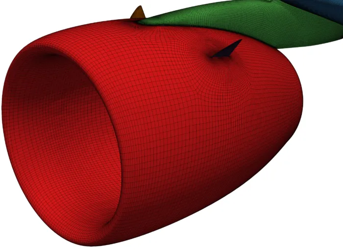
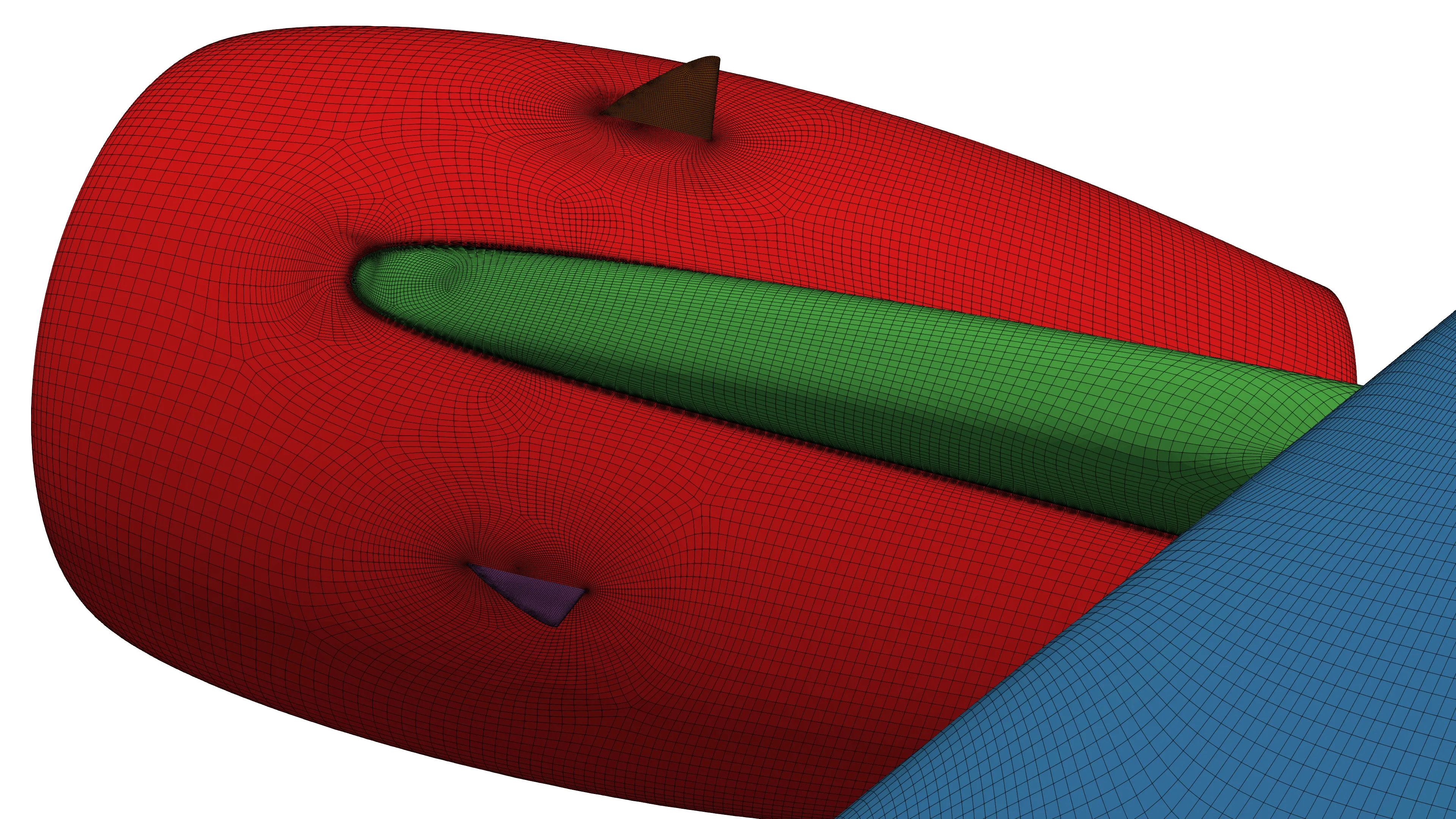
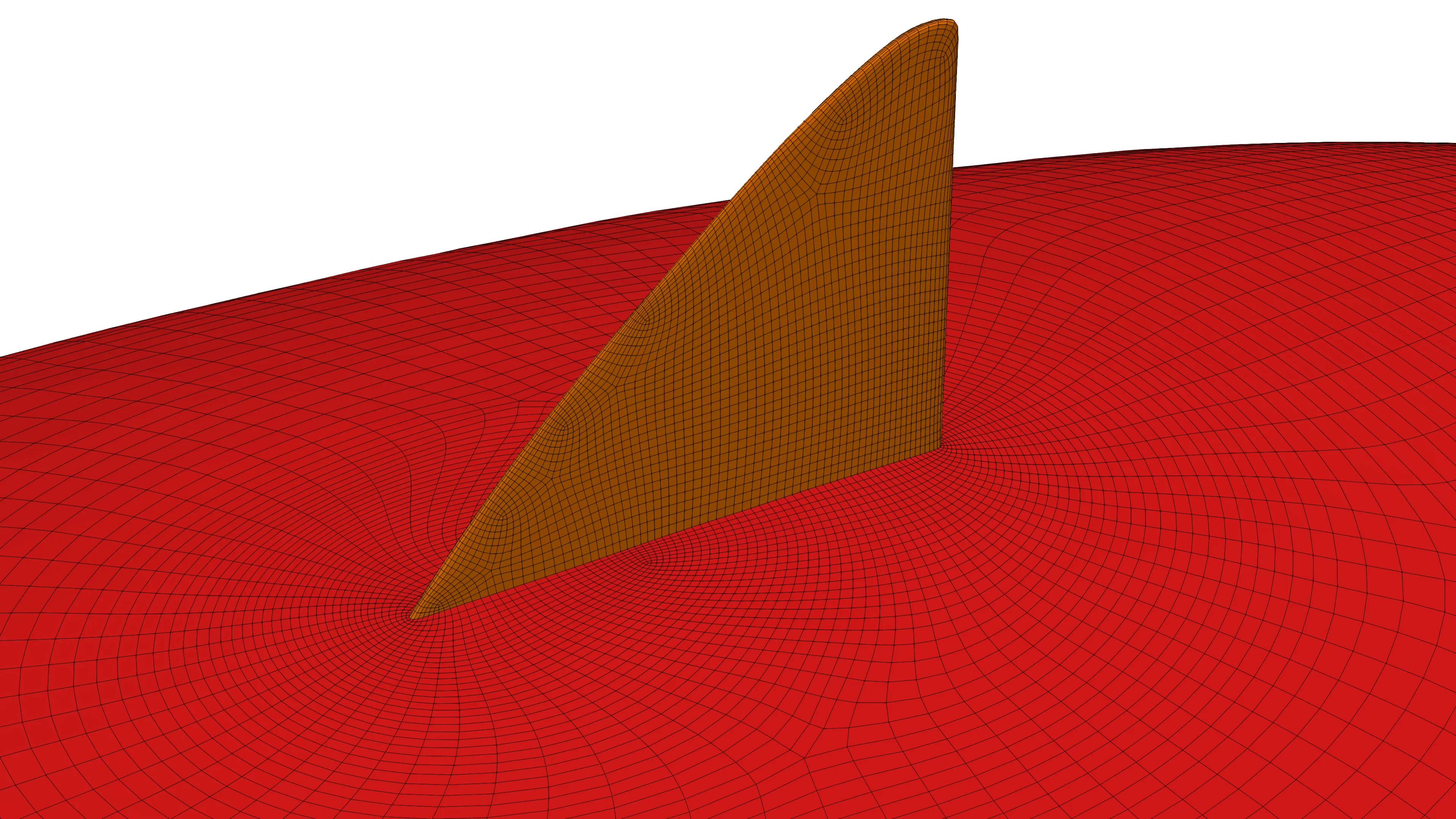
Figure 1: Structured multi-block meshing for aircraft vortex generators – the nacelle strakes.
1100 words / 5 minutes read
Introduction
In modern transport aircraft, underwing engine nacelle installation is the most common design choice. Here, the engine nacelles which are tightly coupled with the wing have a huge impact on the maximum lift and stall angle of the wing. With the usage of larger by-pass ratio engines over the years, the adverse effects of the nacelle on the wing’s performance have increased dramatically, especially so when the high lift devices are deployed.
The nacelles hamper the wing’s desired performance by triggering premature massive flow separation on the main element and decrease the CL_max and stall angle. We cover more of this is in our earlier article Engine Nacelle Aerodynamics.
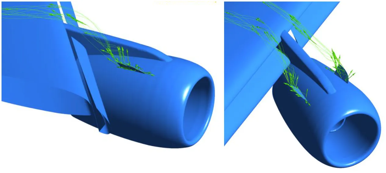
In order to attenuate the negative influence of nacelle, most aircraft manufacturers employ vortex generators called strakes or more popularly known as chines at appropriate locations on the nacelle.
Nacelle strakes are small delta-shaped or triangular panel sheets positioned strategically on the nacelle to induce longitudinal vortices. In short – vortex generators mounted on nacelles are called strakes.
Usually, a pair of strakes are mounted on the nacelles to generate additional vortices to control the flow separation on the wing. Depending on the mounting location and the nacelle-pylon-wing flow field, the generated strake vortices can avoid the generation of slower nacelle vortex or sometimes even interact with nacelle vortex and increase their axial core speed. Thus they affect the position and strength of the installation vortices leading to an increase in maximum achievable lift. Since strakes directly influence the wing’s lift generation capabilities, their design demands careful attention.
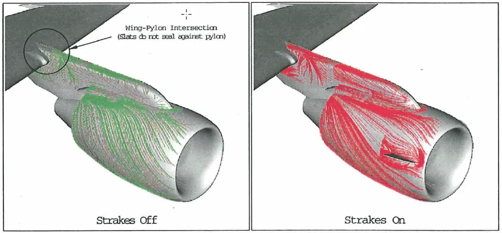
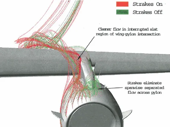
Effectiveness of strake installation
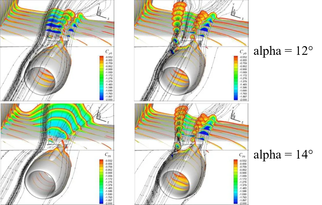
For underwing nacelle configurations without strakes, at alphas near to stall, a large zone of low energy flow gets set above the main wing. The creation of this low energy zone is due to the nacelle blocking the flow from passing over the upper surface of the wing at high alphas. Any further increase in the angle of attack results in premature flow separation.
Parametric design of nacelle strake
The effectiveness of the strakes is directly related to the strake’s geometry and installation location. The strength and trajectory of the strake vortex depend on the strake area, deflection angle, axial position, and azimuth location.
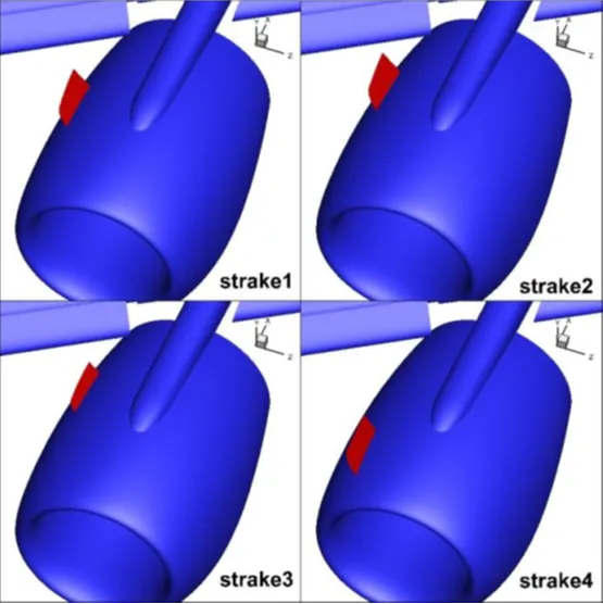
Also, strake 2 and strake 3 have the same exact position, but strake 3 has an area that is two-thirds that of strake 2. Since the location is the same, there is hardly any difference in lift coefficients between strake 2 and 3, before stall. However, after the stall, the strake with a smaller area (strake 3) produces an abrupt drop in lift coefficient.
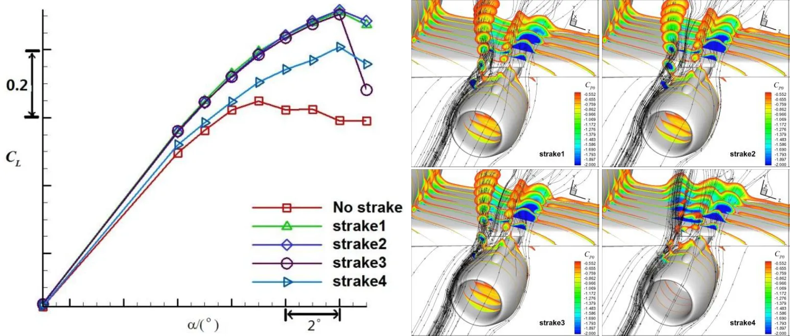
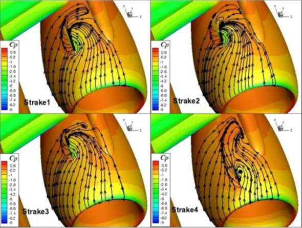
With these observations, we can conclude that the axial positioning of the strake determines the circumferential component of the flow, which in turn determines the strake’s local angle of attack. For a fixed azimuth positioning, the local alpha is a key factor influencing the strength of the vortex. In turn, strake’s vortex strength is a key factor in strake’s effectiveness in delaying the stall.
Parting thoughts
Even though aircraft vortex generators, the nacelle strakes are proven devices to enhance lift for underwing mounted nacelle configurations, they are observed to be less effective for larger UHBR nacelles. For larger bypass ratio engines, they are unable to energize the flow sufficiently and make the flow remained attached to the wing surface. For such nacelles, researchers are working on developing active flow control devices such as pulsed jet blowing to control flow separation.
Nevertheless, strakes which are successfully deployed by all aircraft manufacturers around the world for many decades, will continue to be in use for small and medium-sized aircraft because of their simplicity, cost-effectiveness, and more importantly for their effectiveness in controlling the flow.
Further Reading
References
1. “Modelling the aerodynamics of propulsive system integration at cruise and high-lift conditions”, Thierry Sibilli, PhD Academic Year: 2011-2012, Cranfield University.
2. “CFD Prediciton of Maximum Lift Effects on Realistic High-Lift-Commercial-Aircraft-Configurations within the European project EUROLIFT II”, H. Frhr. v. Geyr et al, Second Symposium “Simulation of Wing and Nacelle Stall”, June 22nd – 23rd, 2010, Braunschweig, Germany.
3. “Navier-Stokes Analysis of a High Wing Transport High-Lift Configuration With Externally Blown Flaps”, Jeffrey P. Slotnick et al, NASA.
4. “Numerical Research of the Nacelle Strake on a Civil jet“, Wensheng Zhang et al, 28TH International Congress of the Aeronautical Sciences, ICAS 2012.
Really informative article.