
Figure 1: Structured multi-block grid for turbopumps.
1050 words / 5 minutes read
Turbopumps help rockets achieve high power to weight ratio by feeding pressurized propellant to the rocket’s combustion chamber. The success of rocket launch missions is heavily influenced by the design of inducers in the turbopumps.
The Rocket Challenge

Human conquest of space has advanced at full speed over the last few years. According to Forbes, there are 10,000 space companies globally. This massive growth has triggered competition in the global space transportation business which is fueling innovations. Reports indicate that nearly 59 % of rocket launch failures are due to propulsion system failures. In this article, we will discuss how the industry is focused on increasing reliability and reducing the cost of development of launch vehicles by improving the design of liquid-propellent rocket engines.
The main reason for propulsion system failure is due to instabilities in the combustor or turbopump. It is estimated that up to 50% of a rocket development program’s cost goes into the design and development of turbopumps.
Failed Missions
Despite many years of extensive research, unsteady cavitation instabilities in turbopumps are a significant problem and are not entirely understood. Further, there are no well-established procedures for predicting its onset during the early design phase.
Cavitation instabilities that can trigger severe load and vibrations within turbopumps cause engine thrust fluctuations and sometimes even total mechanical failure. Historically, cavitation instabilities have caused failed missions in almost all rocket development programs, including Apollo (NASA), Space Shuttle main engines (NASA), Fastrac (NASA), Vulcain (ESA), and LE-7 (JAXA).
Hence, it is critical to identify the mechanisms governing cavitation instabilities to pave the way for building principle-based design guidelines for inducers to suppress cavitation instabilities in turbopump. The beneficial outcome of this exercise will be – more affordable, reliable, and higher-performance turbopumps.

Why Turbopump in Rockets?
Liquid oxidizers and fuels like hydrogen or methane must be fed into the combustion chamber at a higher pressure than the existing chamber at a sufficient flow rate. It is done either by having pressurized tanks or by using a pump. Pressurized tanks tend to be heavy and bulky and are less preferred since they add to the overall rocket system weight.
On the other hand, turbopumps serve as a better alternative due to their compact nature and low weight. Rockets can achieve a high power-to-weight ratio since turbopumps only need a lightweight, low-pressure feed tank.
Challenges in Turbopump Design
One of the main goals of a rocket designer is to stretch the maximum possible delivery payload. Maintaining high thrust chamber pressure and reducing the inert weight of the rocket to a minimum can help achieve this goal. Reduction in system weight is possible by lowering the turbopump size and mass. But, to maintain the same pressure and flow rate, the turbopump needs to run at a high rotational speed. Unfortunately, running at high speed leads to cavitation problems. Coming up with ways to mitigate this issue is a critical design challenge.
The second design challenge arises when the turbopumps are expected to work in off-design conditions. Such a need arises because rocket engines often face varying thrust requirements during their flight. For example, the designer needs to make appropriate design decisions to alleviate the problems of vibrations due to cavitation when the liquid pressure is lowered below the vapour pressure limits. Hence, coming up with ways to reduce performance degradation under cavitation conditions is essential.
Other design challenges which come in more significant magnitudes, unlike in compressors include, high radial and axial thrusts, leakages, increased disk friction, etc. It is up to the designer to develop tricks to manage the tradeoffs and make specific design choices to overcome these problems.

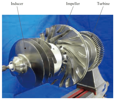
Importance of Inducer in Turbopumps
Designing small and compact turbopumps rotating at high speed can reduce the total weight of rockets. However, at higher speeds, cavitation onsets, causing machine noise and vibration, erosion, loss of head and efficiency, etc.
An anti-cavitation component called the inducer is axially placed upstream of the impeller to overcome these challenges. The inducer, acting as a pre-pump, increases the pressure of the fluid by a sufficient amount to minimize cavitation and improve the performance of the impeller. They are sometimes expected to sacrifice themselves to safe-guard the impeller blade from cavitation.
Unlike the impeller, the inducer blades are fewer in number and are lengthier and wider. Further, they have larger stagger angles, increasing pitch between blades, high blade solidity, and usually small angles of incidences.
With these unique features, inducer blades have minimal blockage due to cavitation, thereby allowing them to operate under very low suction pressure conditions without deteriorating the pump performance. In general, inducers have a minimal effect on the efficiency and head of the pump but offer a dramatic impact on the cavitation performance. Further, they reduce noise and vibration. But more importantly, inducers decrease the pump’s critical NPSH by more than three times.

Parting Remarks
Cavitation surge and inlet backflows are inevitable in turbopumps. All we can think of is finding ways to suppress them to some extent. Suppression can be done by using an obstruction plate or by connecting a smaller diameter suction pipe upstream of the inducers. Backflow suppression helps to narrow the onset range of cavitation surge. Even if they occur, their amplitudes are weakened and subdued by the suppression devices. This helps in achieving improved surge performance.
However, these two suppression techniques are effective when the flow rates are healthy but show their limitations at extremely low flow rates. Researchers recommend combining these suppressing methods with inducer blade shapes suitable for reducing inlet backflows for such extreme conditions.
Further Readings
- Meshing of Rocket Engine Nozzles for CFD
- Spiked Blunt Bodies for Hypersonic Flights
- Know Your Mesh for Reentry Vehicles
References
1. “Studies of cavitation characteristics of inducers with different blade numbers“, Lulu Zhai et al., AIP Advances 11, 085216; 12 August 2021.
2. “Numerical and experimental study of cavitating flow through an axial inducer considering tip clearance“, Rafael Campos-Amezcua et al., Proc IMechE Part A: J Power and Energy 227(8) 858–868, IMechE 2013.
3. “Suction Performance and Cavitation Instabilities of Turbopumps with Three Different Inducer Design“, Tatsuya Morii et al., International Journal of Fluid Machinery and Systems, Vol. 12, No. 2, April-June 2019.
4. “A Study on the Design of LOx Turbopump Inducers“, Lucrezia Veggi et al., International Symposium on Transport Phenomena and Dynamics of Rotating Machinery Maui, Hawaii, December 16-21, 2017.
5. “Study on Hydraulic Performances of a 3-Bladed Inducer Based on Different Numerical and Experimental Methods“, Yanxia Fu et al., Hindawi Publishing Corporation International Journal of Rotating Machinery, Volume 2016, Article ID 4267429.
6. “Study on inducer and impeller of a centrifugal pump for a rocket engine turbopump“, Soon-Sam Hong et al., Proc IMechE Part C: J Mechanical Engineering Science 227(2) 311–319, IMechE 2012.
7. “Turbopump Design: Comparison of Numerical Simulations to an Already Validated Reduced-Order Model“, A Apollonio et al., Journal of Physics: Conference Series 1909 (2021) 012029, ISROMAC18.
8. “Effect of leading-edge sweep on the performance of cavitating inducer of LOX booster turbopump used in semi cryogenic engine“, Arpit Mishra et al., IOP Conf. Series: Materials Science and Engineering 171 (2017).
9. “Design and Analysis of a High Speed, High-Pressure Peroxide/RP-1 Turbopump“, William L. Murray et al., AIAA paper.
10. “A Body Force Model for Cavitating Inducers in Rocket Engine Turbopumps“, William Alarik Sorensen et al., MS Thesis, Massachusetts Institute of Technology, September 2014.
11. “Rocket engine inducer design optimization to improve its suction performance“, M. J. Lubieniecki, M S Thesis, Delft University of Technology, 7 December 2018.
12.” Modeling Rotating Cavitation Instabilities in Rocket Engine Turbopumps“, Adam Gabor Vermes, M S Thesis, Delft University of Technology.