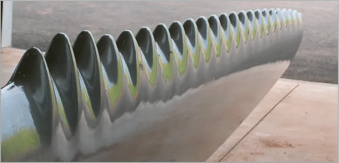
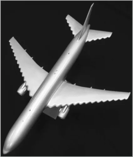
Figure 1: Tubercule wing design variants for the NASA CRM configuration.
1875 words / 9 minutes read
Hit a Roadblock
Engineers for over 100 years have been on the lookout for improving the performance of the lifting device –blades used in aircraft, wind turbines, compressors, axial pumps, fans, etc. Modifications in airfoil contours, add-on devices like flaps, slats, vortex-generators, fences, winglets, shrouds, etc., have improved the blade performances in different conditions. And yet, there hasn’t been one single device that can deliver all the goodies without asking for compromises on other essential performance characteristics. It’s a no-surprise that the design of blades is considered as an amalgamation of compromises.
Hitting a roadblock in making further significant improvements, engineers are now turning to nature for inspiration and in particular to the gentle giants of the ocean – the humpback whales.
Is Whale a Gymnast?
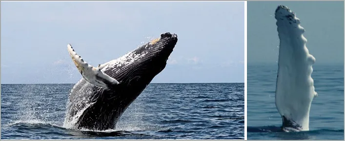
Humpback whales are one of the largest living animals on earth. Growing in size up to 12-16 m in length and weighing 25-30 tons, these mammals are surprisingly very agile. They perform underwater acrobatic feats like rolls, loops, and flips while catching their prey. Whale researchers believe these maneuvering abilities are primarily due to the bumps on the leading edge of their flippers called tubercles.
Because of their large size and weight, they can’t use their bodies to swim like dolphins or porpoises. Instead, they rely on their tails to propel forward and flippers to turn and flip. Like aircraft, they risk stalling and sinking if they try to move fast or turn quickly at high angles.
To overcome this fluid flow problem, nature through millions of years of evolution has come up with tubercles, which aid the flippers in generating continuous lift and maintain stability at all times. These leading-edge humps regulate the pressure distribution on the flippers to ensure that different parts of the flipper stall at different pitch and avoid abrupt catastrophic stalls. This evolutionary modification, increases the whale’s maneuvering abilities, allowing it to attack at higher angles and yet maintain stability.
Inspired by these findings in nature, modern engineers are working to replicate humpback’s tubercles in designing the next generation of aerodynamic and hydrodynamic vehicles.
A Novel Flow
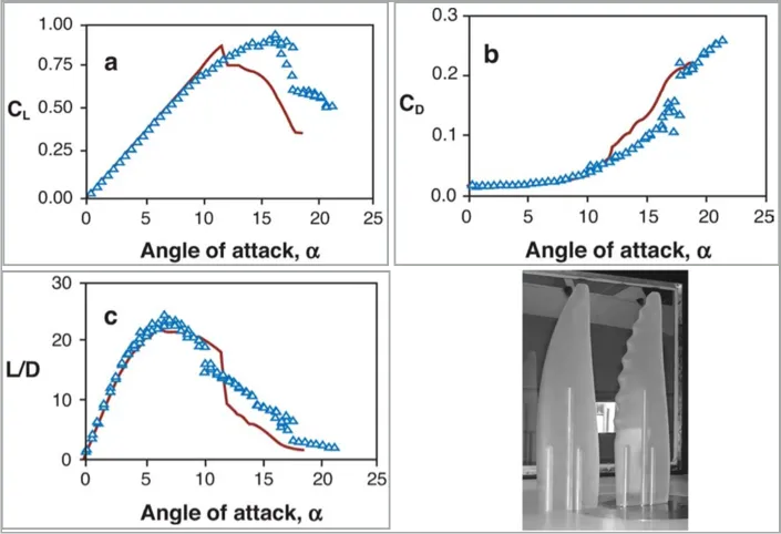
Wind tunnel and CFD simulations have confirmed that the tubercles are indeed a revolutionary design in fluid flow management. It is observed that tubercle wings generate higher lift with reduced drag, always stall gradually, achieve higher stall angles than conventional wings, attenuate span-wise flows and tip stalling, and induce lower noise and vibration.
These performance characteristics make the tubercle wing design very quiet, very efficient, hyper-stable, and a smooth gradual stalling device.
What these performance characteristics mean is that tubercle wing design can operate at a significantly larger pitch angle than normal wings, thereby aiding the wing to generate more lift. More lift, reduced drag, and a gradual stall is the ideal blade performance any aerodynamicist looks for and tubercle blades perfectly deliver it on dot.
Let’s Take The Lid Off…
On a closer look at the flow physics, researchers have observed that tubercles appear to function in a manner similar to vortex generators. Like vortex generators, they too generate counter-rotating vortices that energize the boundary layer flow, compelling the fluid to hug the wing surface and thereby aiding the wing to generate lift at higher alphas.
However, there is a fundamental difference: Tubercle blades increase lift and lower drag whereas, vortex generators increase lift and drag simultaneously. This implies, vortex generators at best can offer limited gains in aerodynamic efficiency, while tubercles paying a substantially lower drag penalty, easily outperforms vortex generators.
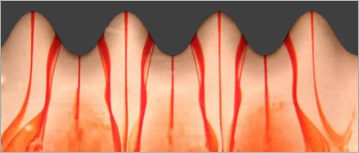
Another physical reason for the better performance of tubercle blades is the larger suction pressure than in conventional straight leading-edge blades when the blade goes into a stall. In a way, tubercles play the dual role of a flow management system as well as that of a stall-control system. Figure 5, shows counter-rotating spirals originating from the leading edge humps of a hydrofoil in a water tank.
The 3D Effect
Interestingly, the superior performance of tubercles is observed only in truly 3D semi-span wings. On infinite 2D wings, laminar straight leading edge wings outperform the tubercles. However, even though semi-span tubercle wings attain lesser Cl_max, they tend to generate substantial lift even after stall, resulting in a gradual stall.
This difference in 2D and 3D planform performance arises because, in 2D, the vortical flows reduce the effectiveness of the wing by triggering early separation, but on 3D semi-span wings, they enhance the effectiveness by inhibiting span-wise stall progression.
In pre-stall alphas, both show similar trends i.e. decrease in lift and increase in drag. However, in post-stall, they show opposite trends – the 3D semi-span wings show increasing lift and decreasing drag while the 2D wing shows decreasing lift with increasing drag. In a way, the development of vortices by tubercles is truly beneficial only in 3D plan forms.
Attenuation of Span-Wise Flow
Another remarkable aspect of tubercle leading edges is, they enhance the effectiveness of the semi-span wings by preventing span-wise stall progression. This is important because aerodynamic efficiency reduces considerably with span-wise pumping and tip stall.
Usually, on laminar flow blades, span-wise flow sets in when air detaches from the surface and starts to flow towards the tip. This change in flow pattern disrupts the attached flows along the span and increases the drag. This damaging effect becomes even more severe when it leads to tip-stall. Tip-stall literally wastes the power-generating potential in the air, when it pushes the air stream off the edge of the blade tip.
In aircraft, this phenomenon not only reduces the aerodynamic efficiency but also increases fuel consumption. It’s for this reason, modern wing designs have winglets at their tips and rotating aerodynamic blades like compressors, gas turbines, axial pumps, fans have shrouds to block air flowing off the tips.
The damages due to the tip stall don’t end there. Sudden, abrupt separation of the vortices at the tip generates blade vibrations along with audible and very low-frequency subsonic noises. It is reported that nearly 85 percent of the noise in wind turbine blades is caused by tip-stall. If left unattended, the powerful vibrations will trigger blade degradation, laminate de-bonding and in the worst case– break the blade itself.
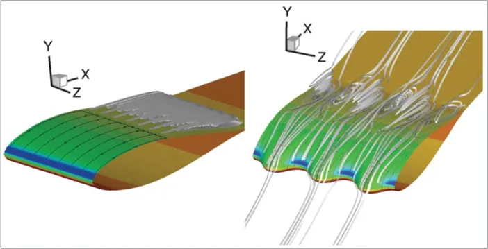
Tubercles without the need for any physical structural modifications at the wing tips very effectively attenuate the span-wise flow and tip-stall. The chord-wise channular flow which gets set up around the humps creates virtual fences, which break up the separation regions and halt the span-wise movement of flow.
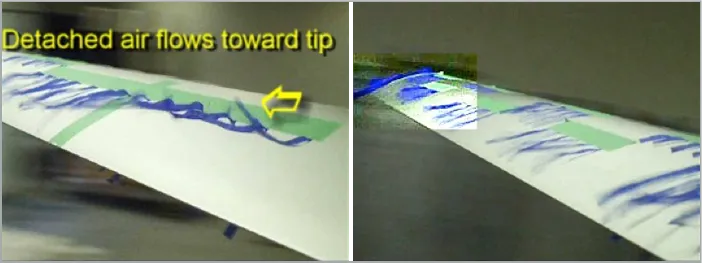
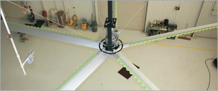
Figure 6, shows this phenomenon in action for a wing design with tubercles at the leading edge for the outer 60 percent of the blade span. The green chord-wise tape shows the location from where the tubercles begin. On a normal straight blade, span-wise flow with tip-stall is observed for a pitch angle of 22 degrees rotating at a speed of 55 rpm. On this tubercle blade, when the span-wise flow reaches the green tape line, it gets halted abruptly, forced to change direction, and made to flow chord-wise. Figure 6b shows the continuation of this corrected flow pattern all the way to the blade tip.
Application Areas
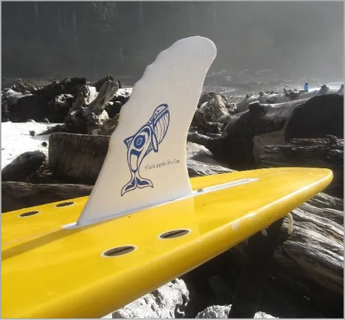
Research studies in understanding the flow-physics around tubercle wing design have been going on for the last 10 years and it is only now that this technology is garnering acceptance and making its way into the design of various control surfaces like rudders, wings, fans, propellers, tails, sailboat keels, fins, skegs, etc.
One of the primary areas where tubercles perfectly fit in is wind turbine blade design. It is reported that tubercles respond better to rapid changes in wind speed. Unlike the conventional blades, tubercles have the unique ability to eke out power even from low-speed wind. They easily increase the power generation capacity of the windmill by 20 percent and greatly reduce the noise due to tip chatter.
When introduced in industrial ceiling fans used in large buildings like dairy barns, factories, warehouses, etc., tubercles help to increase air circulation by 25 percent while consuming 20 percent less power than a conventional blade. In addition, these tubercles fans are 20 percent less noisy, as they suppress the tonal noise.
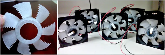
On a smaller scale, these humps show their performance-enhancing abilities in cooling computer components, where they are found to be 20 percent more efficient than regular blades.
Several aerospace companies are also actively researching this device to build next-generation safer, stable, highly maneuvering vehicles. Since tubercles delay stall at high alphas, they can potentially replace boundary-layer control devices like flaps and slots which are used during landing and takeoff of conventional aircraft. Elimination of these devices will significantly reduce aircraft weight and thereby increase fuel economy.
Concluding Thoughts
There is a lot to learn from nature. The field of biomimicry does this by learning, appreciating different aspects of nature, and figuring out ways to mimic it in human endeavors. In many cases, a straight forward transition of understanding to human needs is not possible as the scales, conditions, and requirements of human applications are much more varied and complex. However, in this case, the tubercle technology from humpback whales can be directly used for various hydrodynamic and aerodynamic applications without any modifications.
Odd as it may seem, we humans have been rampantly killing these species for decades, pushing them to the brink of extinction. However, when we have hit saturation in our developmental progress, these gentle giants stand up to offer solutions.
Further Reading
- The Art and Science of Meshing Airfoils
- Shape Optimization for CFD-101
- Engine Nacelle Aerodynamics
- Role of Vortex Generators in Diffuser S-Ducts of Aircraft
Reference
1. “The Tubercles on Humpback Whales’ Flippers: Application of Bio-Inspired Technology”, Frank E. Fish et al, Integrative and Comparative Biology, volume 51, number 1, pp. 203–213, May 15, 2011.
2. “Leading-edge tubercles delay stall on humpback whale flippers”, David Miklosovic et al, Physics of Fluids, May 2004, Volume 16, Number 5.
3. “On the Role of Leading-Edge Bumps in the Control of Stall Onset in Axial Fan Blades”, Alessandro Corsini et al, Journal of Fluids Engineering, August 2013, Vol. 135.
4. “Experimental Evaluation of Sinusoidal Leading Edges”, David Miklosovic et al, Journal of Aircraft 44(4), 1404-1408, July 2007.
5. “Aerodynamic characteristics of wind turbine blades with a sinusoidal leading edge”, R.K. Zhang, Wind Energy 15(3), 407-424, April 2012.
6. “Hydrodynamic flow control in marine mammals”, Frank E. Fish et al, Integrative and Comparative Biology, May 6, 2008.
7. “How Bumps on Whale Flippers Delay Stall: An Aerodynamic Model”, Ernst A. van Nierop et al, Physical Review Letters, January 8, 2008.
8. “Characterization and Design of Tubercle Leading-Edge Wings”, Mark W. Lohry et al, ICCFD, July 9-13, 2012.
9. “Passive and active flow control by swimming fishes and mammals”, Frank E. Fish et al, Annu. Rev. Fluid Mech., 2006. 38:193–224.
10. https://whalepowercorp.wordpress.com