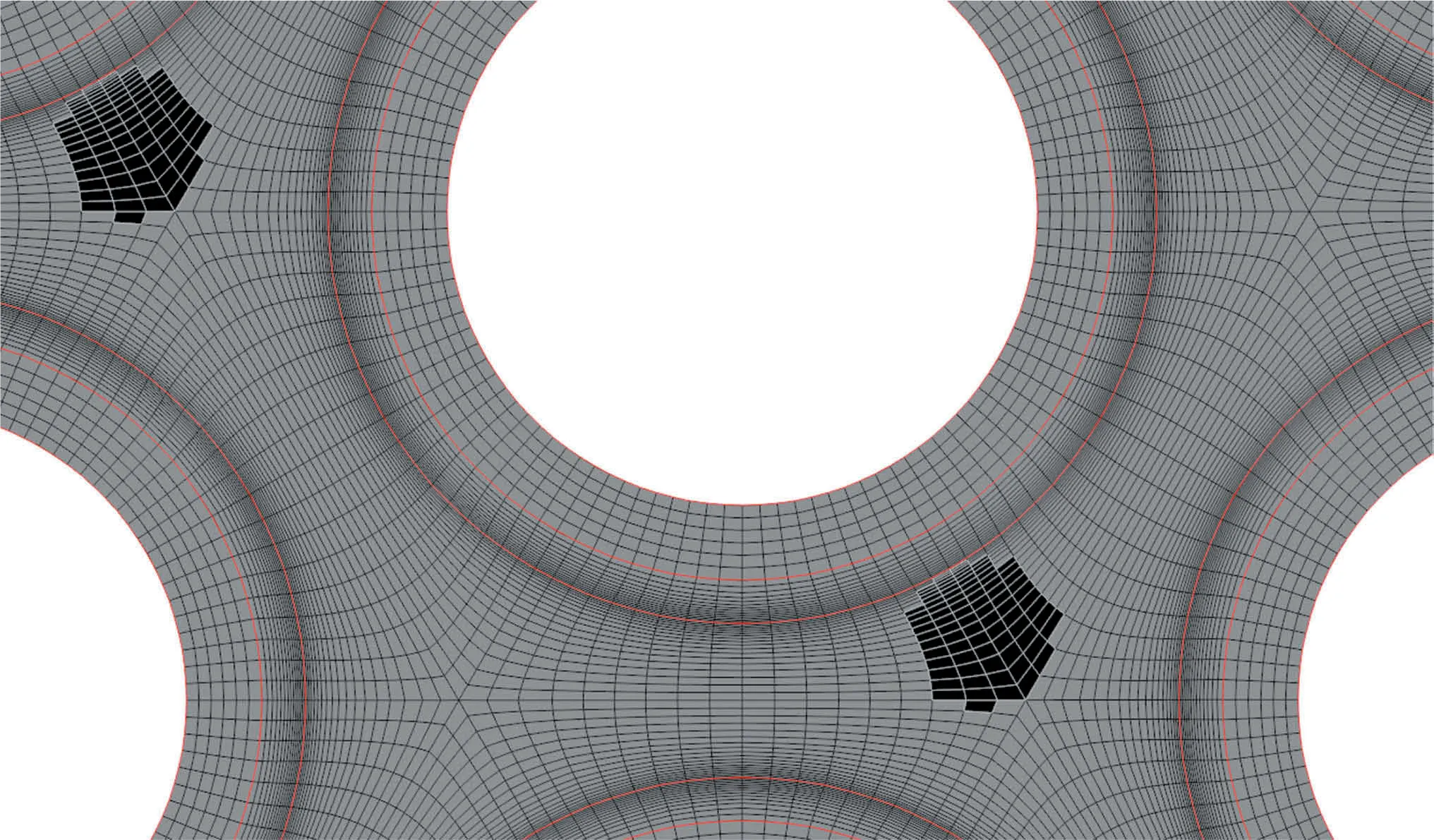
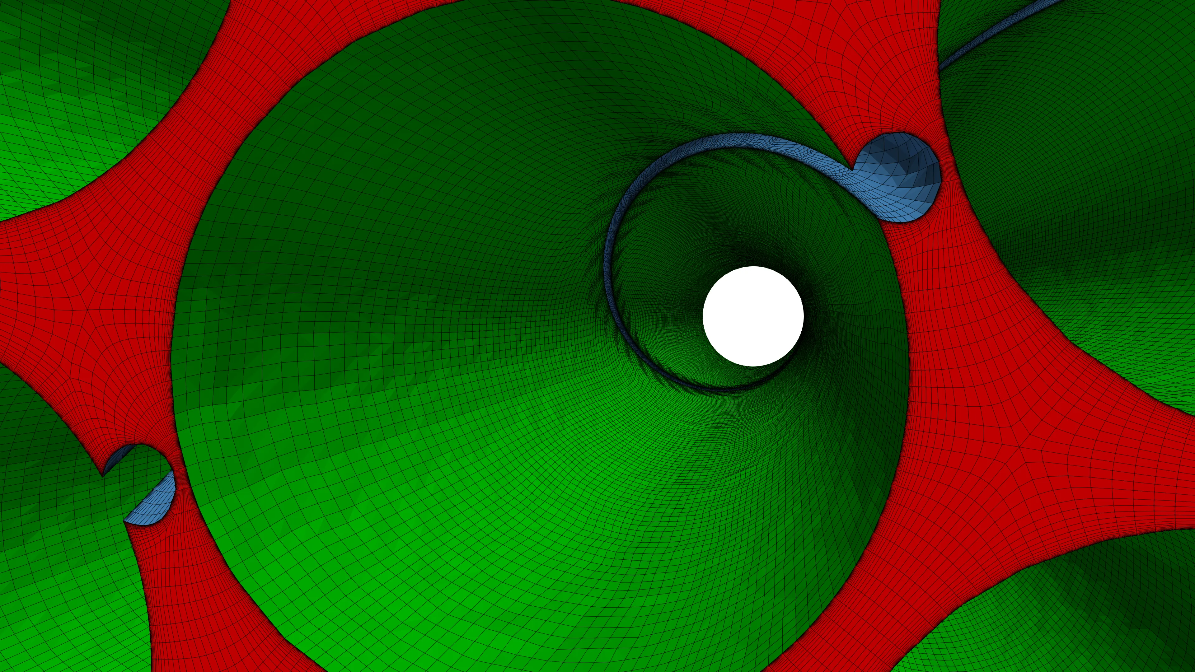
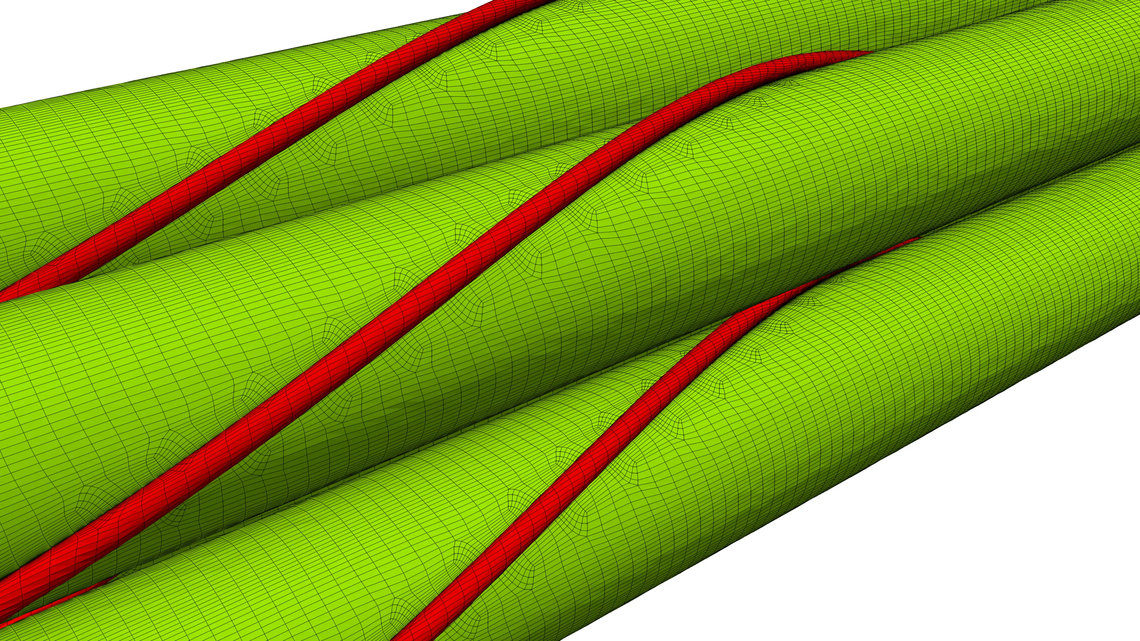
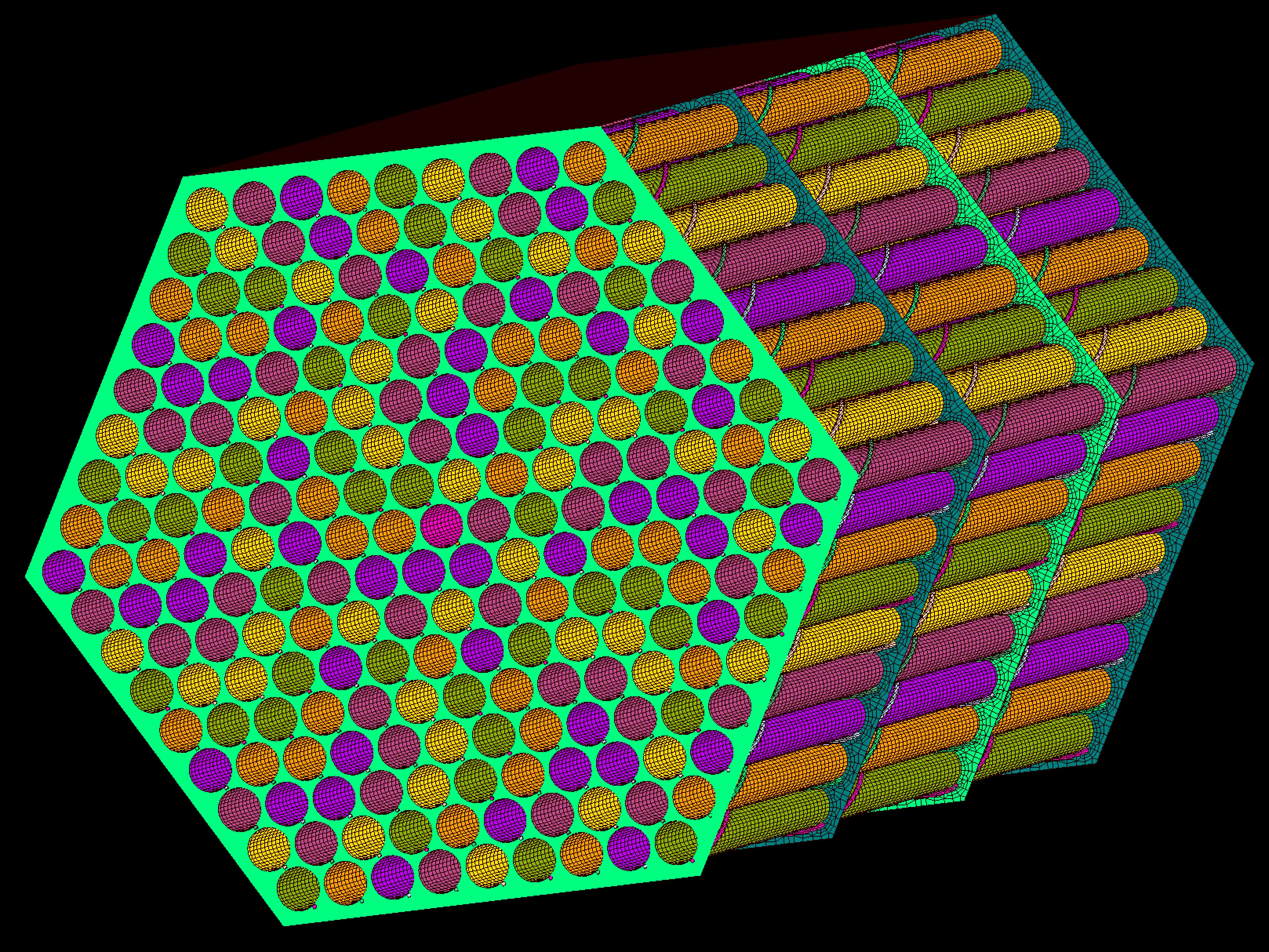
Figure 1: Structured multi-block meshing of a wire-wrapped nuclear fuel rods assembly.
1910 words / 9 minutes read
This is Part 2 of the series on Nuclear Fuel Rods. Part 1 / Part 2 / Part 3.
In Part 1 of the series, we covered aspects of the next generation of fuel-efficient nuclear reactors and the flow physics in wire-wrapped nuclear fuel rods assembly.
In this article Part 2, we try to cover some of the aspects of CFD modeling of the wire-wrapped fuel pins – the challenges, the geometric approximations, gridding requirements, etc.
Introduction
An accurate understanding of the intricate flow fields of fuel rod sub-assemblies is extremely essential for the proper design of these critical nuclear core components considering the high levels of safety requirements needed while operating nuclear power plants. CFD has emerged lately as a reliable computational technique used extensively for design and safety evaluation purposes. Particularly for wire-wrapped fuel bundles, CFD has been pivotal in understanding and appreciating the complex flow physics and thermal-hydraulics.
In fuel-assemblies analysis, CFD is routinely used to compute pressure drop across the fuel bundle, velocity and temperature distribution, quantifying hot-spot temperatures, and heat flux distribution.
Geometrical modeling and discretizing the flow field around the helical wire wound fuel rods is very intricate and poses a significant challenge. For the accurate resolution of the flow features, the configuration demands a mesh with a massively large number of grid points. This means, a need for larger computer memory and time. The more the number of fuel rods considered for CFD simulation, the larger is the requirement for computational resources.
Video 1: Pressure distribution in a 217-pin fuel bundle with wire-wrapped spacers. The Nek5000 simulation calculations were run with 3 million spectral elements of order N=7 (one billion points total) with sustained 80% parallel efficiency.
Typically, nuclear reactors utilizing wire-wrapped pins, pack them in bundles of up to 217. Modeling with 217 rods is very expensive. So, researchers often make use of a smaller bundle size ranging from 7 to 61 rods. However, one has to ensure that using a smaller bundle does not significantly alter the flow physics. Studies addressing this issue have shown that using at least 19 pins weakens the influence of the number of pins and effectively captures all the predominant flow physics.
Geometric Approximations
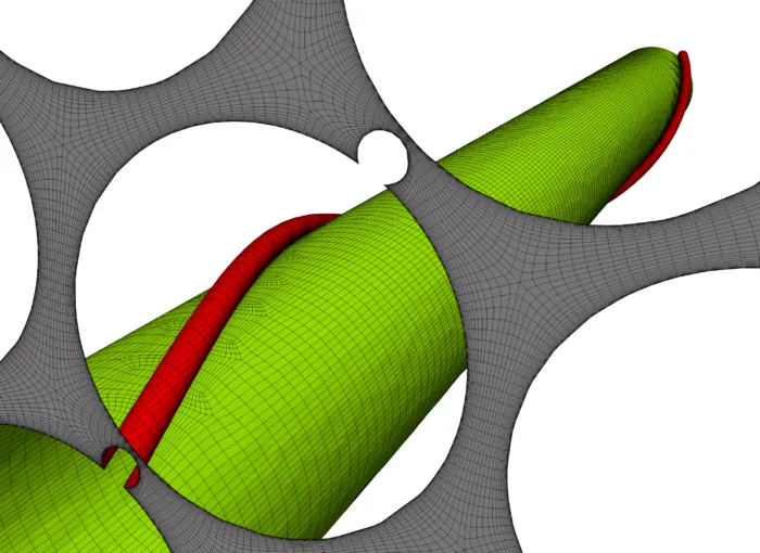
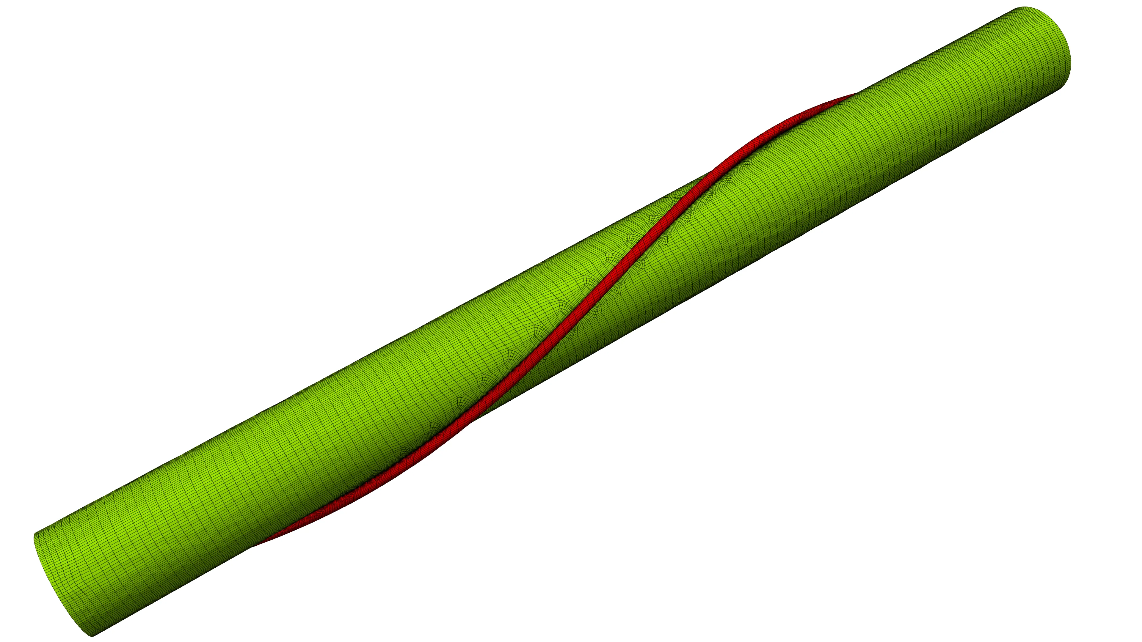
Accurate capturing of the helical wires is very essential. The wires which help in suppressing vibrations and prevention of horizontal displacement of the rods, also aid in effective mixing of the coolant, by reducing the temperature gradients and critical heat flux. However, along with these beneficial effects they also induce increased pressure loss. Further, in the wake of the wire, in regions of low velocities, a shoot-up in surface temperature can also occur. It is therefore very essential to model the wire accurately for accurate prediction of hot spots in the vicinity of the wire and drop in axial pressure. What this means is that we need to have good resolution grids with high quality in the vicinity of the wire especially at the contact region between the rod and the wire.
Dr. Michael Böttcher from Karlsruhe Institute of Technology elaborates on the meshing needs for obtaining accurate CFD predictions for wire-wrapped nuclear fuel rod bundles in this talk presented at the Pointwise User Group Meeting.
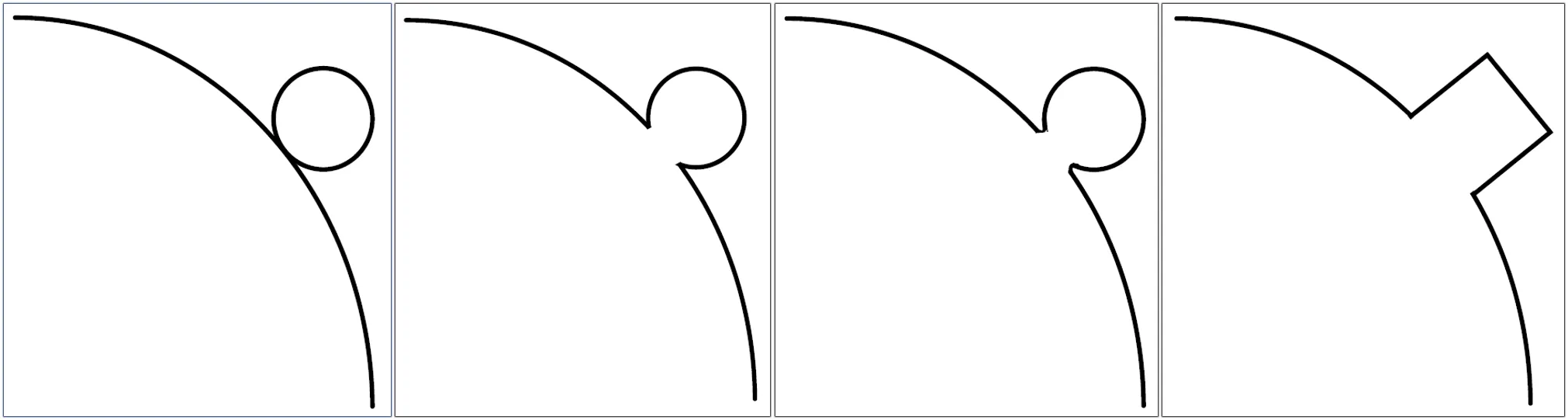
Figure 2 shows four of the most common approaches to model the wire-rod junction. In actuality, the contact between wire and rod is point contact (Figure 2a). Though modeling this is ideal for predicting temperature in the contact zone, it is very difficult to mesh due to tangencies. However, in the second modeling variant (Figure 2), a small radial inward displacement for the wire, say, 5% of the wire diameter is provided. With this small geometric modification, meshing the configuration becomes more feasible. The geometric approximation helps to achieve a homogenous mesh with only a few layers of skewed cells in the acute regions. Which makes it possible for a reasonably accurate prediction of the hotspots region.
Another type of approximation used by researchers to ease the meshing process is the blending between the wire and the rod by filleting (Figure 2c) of the acute region. This geometric variant allows for placing fine meshes of smaller size at the contact zone along with an approximate prediction of the hotspot with small uncertainty. However, depending on the rod-wire contact form, CFD computations have shown to predict a 15% more pressure drop compared to wires with a point contact.
Another make-do approximation is, using a square profile (Figure 2d) with a cross-sectional area equivalent to that of the circular wire. Though this model is easy to mesh, accurate prediction of hotspots is not possible. Also, it is observed that square wires tend to predict 5% increased pressure loss when compared to the model with displaced wire. Interestingly, studies with hexagonal and rhombi forms have also shown to overestimate the pressure drop by a large value of 16% and 19% respectively, relative to the displaced wire approach.
Considering all the merits and demerits of the 4 modeling approaches, researchers feel that the displaced wire approach with a displacement of the wire by 5% of the wire diameter into the rod is an acceptable compromise to model the wire-rod junction.
At times, the entire fuel assembly is considered for CFD analysis, including the inlet and outlet headers. For such large domains, accurate prediction of the flow field with high-resolution grids is not possible. So to reduce the computational effort but still maintain reasonable accuracy, low resolution or under-resolved meshes are used. On occasions, researchers sought out approaches like geometric simplification of the rod bundle by modeling the wire as a spiral fin or as a momentum source. These are approximate methods that need experimental validation.
In the momentum source (MS) approach, the simulations employ meshes of bare pins without the wire-wrap geometry explicitly modeled. Instead, the effect of the wire-wrap on the flow is accounted for by introducing a momentum source into the governing fluid equations. This MS is only applied to cells corresponding to the location of the wire wrap, and its vector components in each cell are based on the local flow field.
This wire simplification method by momentum source is ideal for initial scoping studies of wire-wrapped fuel assemblies, as they reduce computational cost and also avoid complications due to body-fitted meshing of wires. The benefits of this modification can be seen in the quick turnaround time for design modifications.
Gridding Requirements
Accurate prediction of flow fields inside the subchannels demands high-resolution grids. The thin wires wrapped around the rods need to be finely discretized. The small junction where the wire meets the rod needs to have highly refined cells as they are potential locations for hot spots.
The wire-wrapped rods are compactly packed and the space between the rods is fairly narrow. If we want to resolve the flow features developing in these narrow passages, they need to be filled with finely refined cells. The vortices generated in the inner channels, swirling flow in the outer channels, all need good resolution cells.
Along with appropriate discretization of the inviscid flow field, it is equally important to resolve the viscous boundary layer. The flow in the subchannels is viscous-dominated flows. So, fully resolving the boundary layer of the rod as well as the wire is critically essential. Viscous padding with a Y+ of about 1 with a small stretching factor is highly recommended. Good resolution of the boundary layer helps in the accurate prediction of heat transfer quantities and velocity profiles.
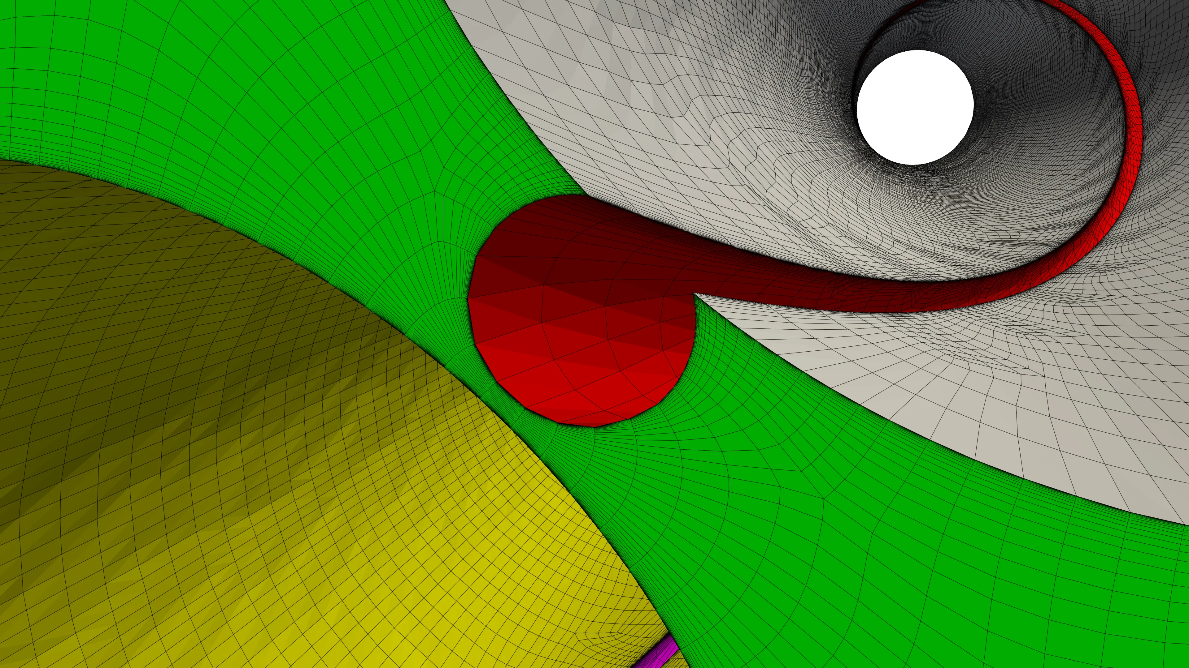
Care should be taken while meshing the small gap between the wire of the parent rod and the neighboring rod. The gap tends to be extremely small and getting good quality meshes with low skewness is very essential.
Because of the helical nature of the wrapped wire and the all-length association with the rod, many CFD practitioners go with unstructured gridding techniques like hybrid, polyhedral or cartesian. Though these approaches are quicker to generate grids, they result in abnormal grid size demanding huge computational resources. Along with that, the unstructured approaches are more dissipative in nature, which smear off the subtle flow features.
It is for this reason, researchers who look for high-quality solutions prefer structured multi-block grids. The flow-aligned nature of grid cell placement, helps in better, crisper capturing of the flow features with less dissipation. Structured approaches, unlike their unstructured counterpart, have the added advantage of employing stretched cells in the axial direction. This not only helps in reducing the cell count drastically but aids in using the cells more optimally by increasing the resolution in the other two directions. The challenge of creating the structured mesh is a tough one, primarily the thought process required to design the blocking structure and the time taken to build such a structure. With recent advances in structured meshing, this challenge has become the problem of the yesteryears.
Figure 8 shows the comparative results obtained by TerraPower corporation, by cell reduction in the axial direction. The fine mesh was axially coarsened to the number of axial cells in the coarsest mesh. Cell reduction of 27 million equivalent to 32% of total cell count was achieved with the same level of solution accuracy as the fine grid.
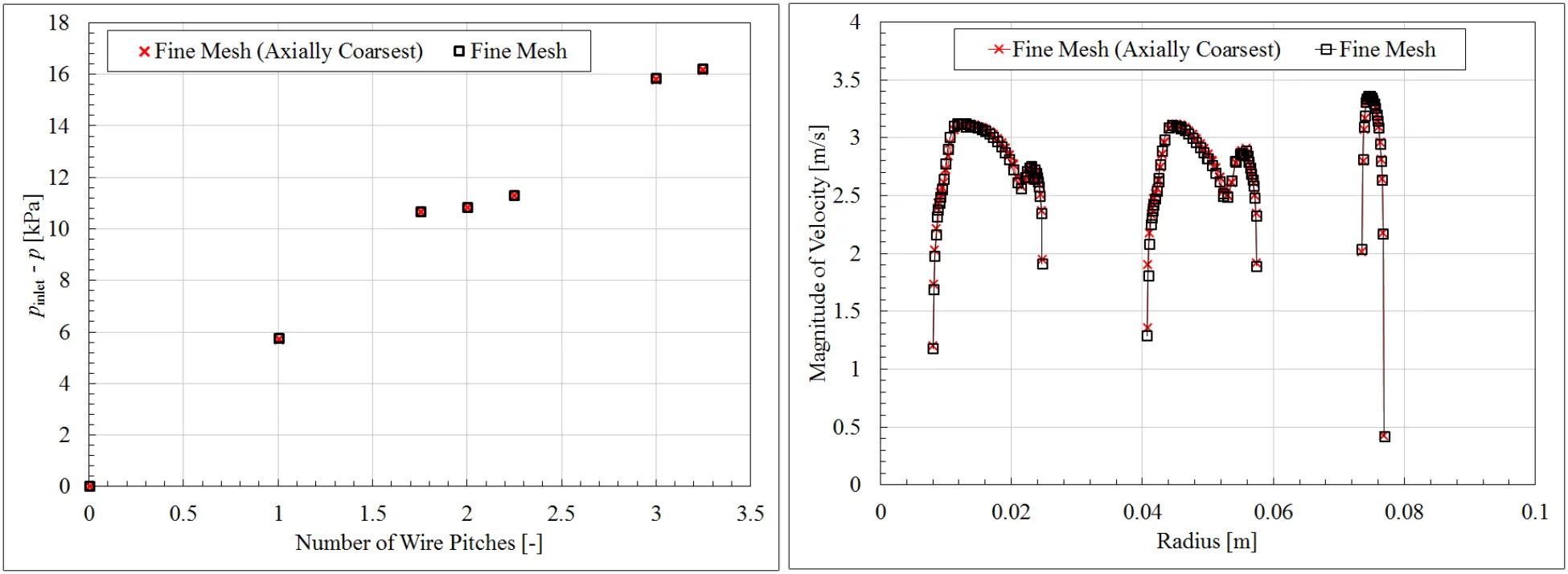
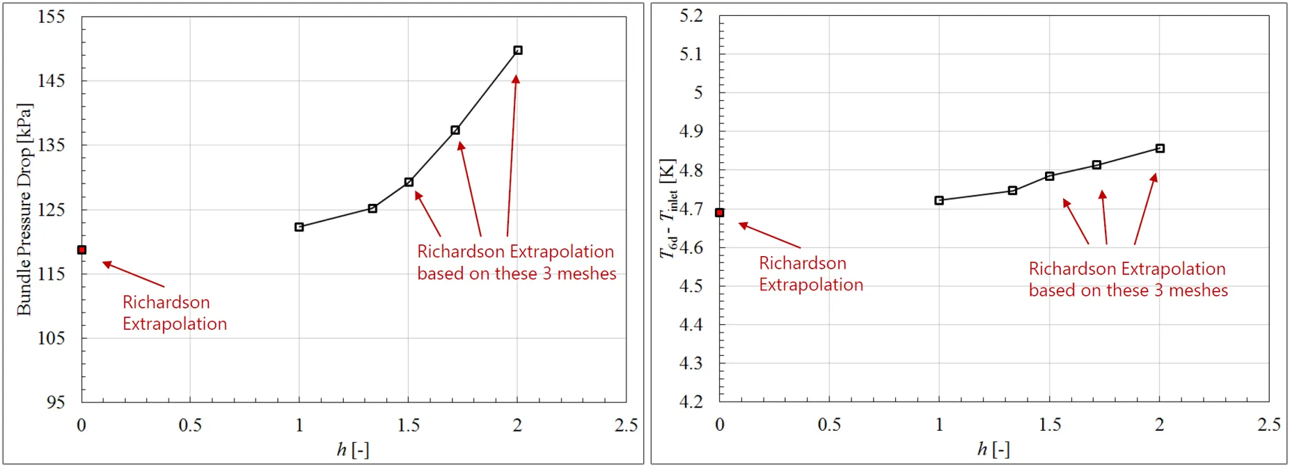
Often, it is very difficult to know what is the right mesh size to get accurate CFD prediction. Under such circumstances, a grid convergence study is conducted. A set of grids sequentially refined are generated and CFD solvers are run to check the level of variation in the flow parameters. Analyzing the results, a grid with an acceptable level of error tolerance is picked for repeated runs. Figure 9 shows a grid convergence study by TerraPower for a fuel rod assembly.
Challenges in modeling a full-scale 217 fuel pin bundle
It is estimated that, for a one-pitch helical wire, the cell count requirements for a 217 pin bundle is 36 times that needed for a 7-pin bundle. If the complete length of the rod is considered the cell count will be 15 times that needed for one pitch. This means, the total cell count will turn out to be around 500 times that needed for a 7-pin bundle, which will come out to be about 200 million. The memory requirements will turn out to be about 200 Gb, while the expected CPU time will be around 2500 hours or ~ 100 days. If we want to make the simulation computationally more feasible, we need to discretize the domain with structured multiblock and use a highly scalable CFD solver.
Parting thoughts
The top priority of nuclear power plants is safety. All safety concerns can be addressed if there is reliable data for all possible scenarios. CFD as a simulation tool helps in giving the Engineers a clear perception of all the possible scenarios in intricate detail. Structured grids with their less dissipative nature, flow-aligned cell placement, reduced cell count help in obtaining high-quality reliable solutions. They not only make computations for smaller fuel rod bundles less time-consuming and computationally cheaper, but they also make the simulation for full-scale 217-rod bundles more affordable.
This brings us to the end of Part 2 in the series on Nuclear Fuel Rods. In the next article Part 3 – Meshing Wire-Wrapped Fuel Rods in GridPro, we cover aspects of generating high-quality structured multi-block grids for various geometric variants of wire-wrapped fuel rod assemblies, automation, etc, using GridPro.
References
1. “Numerical investigation on vortex behavior in wire-wrapped fuel assembly for a sodium fast reactor”, Min Seop Song et al, Nuclear Engineering and Technology 51 (2019) 665-675.
2. “Status and Future Challenges of CFD for Liquid Metal Cooled Reactors”, F. Roelofs et al, International Atomic Energy Agency, March 2013.
3. “CFD investigation of helical wire-wrapped 7-pin fuel bundle and the challenges in modeling full scale 217 pin bundle”, R. Gajapathy et al, Nuclear Engineering and Design, December 2007.
4. “Thermal-Hydraulic study of the LBE-Cooled Fuel Assembly in the MYRRHA Reactor: Experiments and Simulations”, J. Pacio et al, NURETH-16, Chicago, IL, August 30-September 4, 2015.
5. “CFD Investigation of Wire-Wrapped Fuel Rod Bundles and Flow Sensitivity to Bundle Size”, L.M. Brockmeyer et al, NURETH-16, Chicago, IL, August 30-September 4, 2015.
6. “High-Fidelity Numerical Simulation of the Flow Through an Infinite Wire-Wrapped Fuel Assembly”, A. Shams et al, NURETH-16, Chicago, IL, August 30-September 4, 2015.
7. “Verification and Model Sensitivity Analyses for Computational Fluid Dynamics Simulations of Wire-Wrapped Nuclear Fuel Assemblies”, Daniel Leonard, Ph.D. et al, ASME Verification and Validation Symposium, May 18-20, Las Vegas, NV.
8. “The role of High Fidelity Numerical Simulations for Nuclear Reactor Safety Analyses”, Ed Komen, SNETP FORUM, 2 – 4 Februari.
9. ” CFD calculations of wire wrapped fuel bundles : modelling and validation strategies“, Ulrich Bieder et al, NEA-CSNI-R–2011-14, INIS Volume 44, Issue 33, 2012.