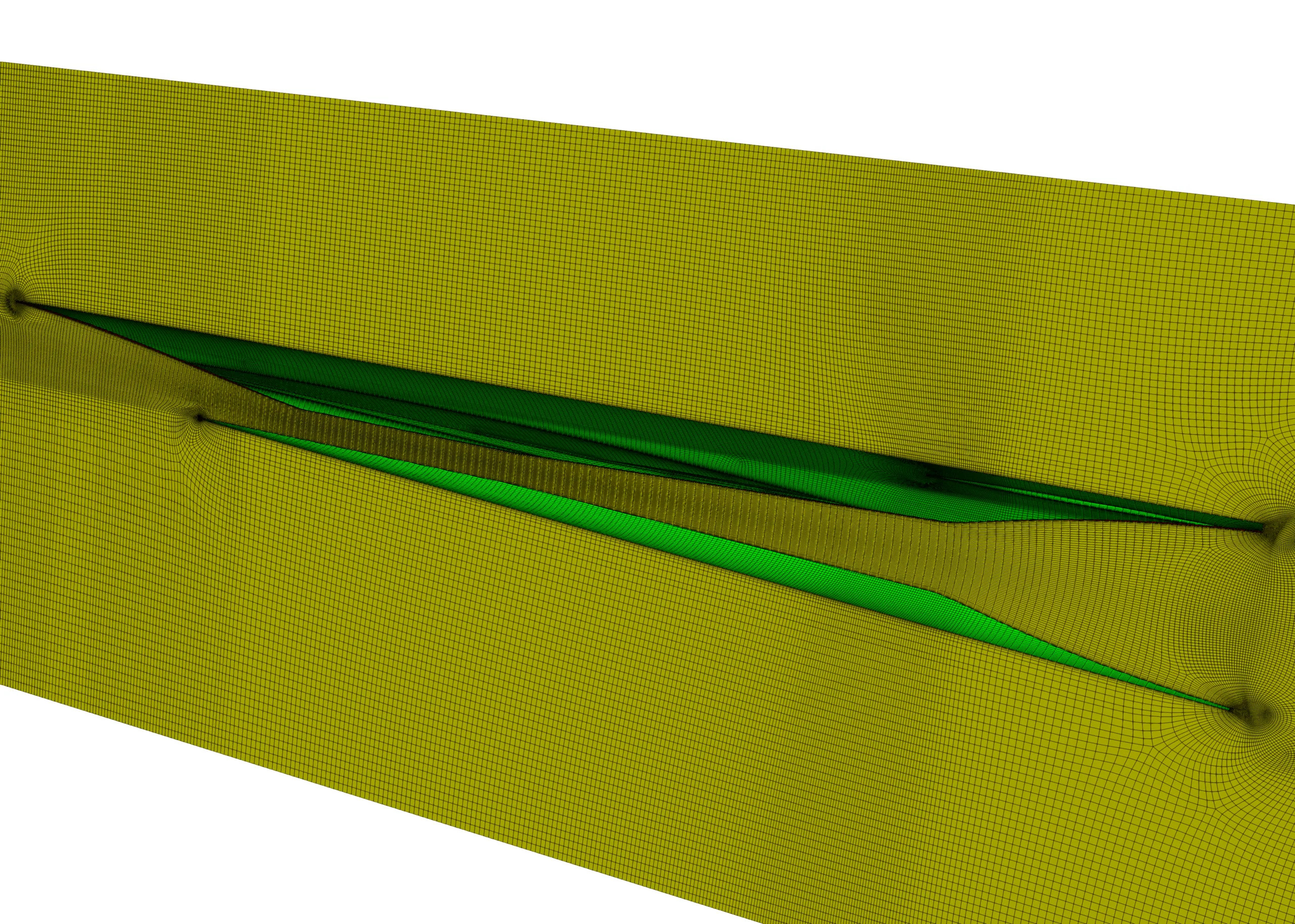
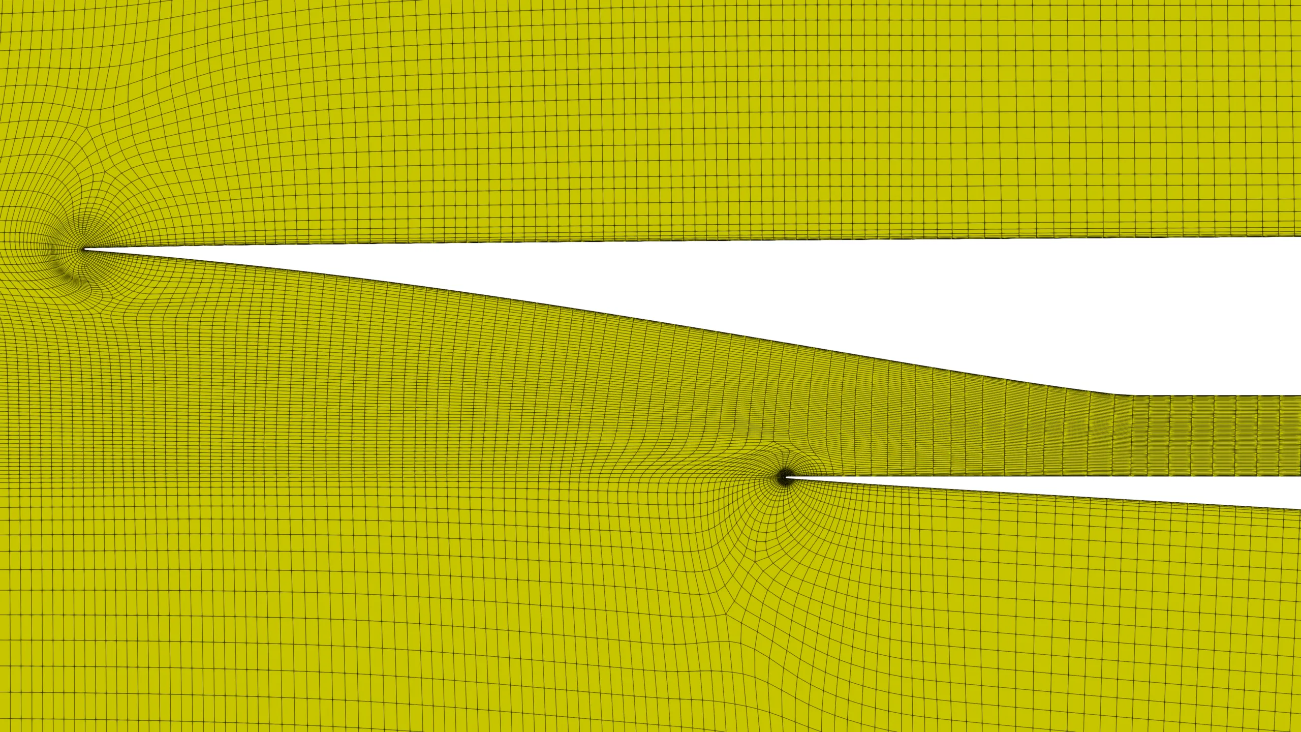
Figure 1: Structured multiblock mesh for a scramjet engine.
1586 words / 8 minutes read
Over half a century has elapsed in designing a working scramjet-powered hypersonic vehicle. Considered harder than rocket engines, designing scramjets is a massive engineering challenge. However, with newer design improvisations such as airframe integration and REST design, scramjet-powered hypersonic flights are close to becoming a reality.
The Buzz About Scramjet Engines
With China and Russia making all the buzz about making successful scramjet-powered hypersonic flights, it looks like the game is on. The West, led by NASA, started the scramjet research in the 1950s. A couple of years into the research, early scientists quickly realized the scientific difficulties of designing scramjets engines. Some say it is harder than rocketry.
This article takes you through the different aspects of scramjet technology, starting with answering the question: what is scramjet, and how is it different from jets and rockets.
What are Scramjets? And how is it different from the Jets and Rockets:
Jets-Ramjets-Scramjets-Rockets
In a jet engine, the flow inside the combustion chamber is subsonic. Even if the jet is flying at supersonic speed, the intake and the compressor slow the air down to low subsonic speed. This increases the pressure and temperature. The higher the flying speed, the higher the rise in pressure and temperatures when we slow the flow down. Normally, in jets, the compressor does the job of raising the pressure and temperature. But if we are moving fast enough, the compressor can be chucked out, and so is the turbine driving it, as just slowing the flow to subsonic conditions will raise the pressure and temperature to the required levels. So, what is left behind without a compressor and turbine is the Ramjet.
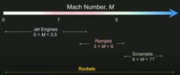
A ramjet is a simple tube with an inlet to capture the air and slow it down, a combustor to inject fuel and burn it, and an exhaust nozzle to expand the combustion products to generate thrust. Ramjets can’t start from 0 speed but need about Mach 3 to get going, and they can operate up to Mach 6. Beyond that, the rise in temperature and pressure due to the ram effect is too high for proper combustion.
As a solution, what can be done is the flow can be slowed down just a little bit, thus raising pressure and temperature, but leave it largely supersonic and see if we can do combustion in it. An engine that does just that is the Scramjet – Supersonic Combustion Ramjet. Scramjets that can start operating around Mach 6 can go up to Mach 12 or 14. The upper limit is up for debate as, near the upper Mach limit, we run into the same issue of too much rise in temperature due to slow-down effects to maintain proper combustion. Additionally, near the upper limit, external drag forces become very high, and the heating problems become even more severe.
Rockets, on the other hand, don’t suck air from the atmosphere but carry their own oxygen. Because of this, they are versatile and can fly in any planetary atmosphere and empty space. At the same time, carrying oxygen makes them heavy and less fuel-efficient. So, scramjet is the most attractive option if one wants to fly at hypersonic speeds in Earth’s atmosphere.
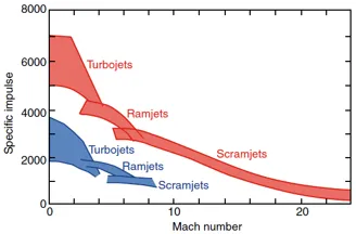
Lastly, if one wants to compare these propulsion systems w.r.t fuel efficiency, turbojets are the most fuel-efficient system for the Mach 0 to Mach 3 range. Between Mach 3 and 6, the ramjets are the better performers, while above Mach 6, scramjets are the best. Rockets, even though can operate over all the Mach number regimes, they have the lowest fuel efficiency as they have to carry the oxidizer with them.
Designing the Scramjet Engines
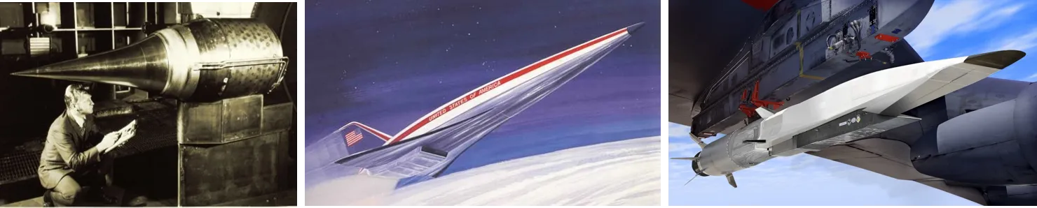
The first generation of scramjet engines had a pod-style design with a large axisymmetric spike for external compression. Bearing similarity to gas turbine engines, scramjet pods were designed independently of the vehicle it was meant to propel. In the end, the design was discarded as the supersonic combustion could not overcome the external drag of the spike, as it lacked the much-needed airframe integration.
Hence, from the second generation onwards, the smooth integration of the engine with the vehicle was done. The vehicle is made long and slender for low-drag purposes, and the scramjet engine, with a 2D flow path, is mounted on its belly. The engine is positioned in the shadow of the vehicle’s bow shock to ensure that the vehicle’s forebody does some part of the air compression before entering the engine. In a way, one can say the vehicle is the engine, and the engine is the vehicle in this design.
Unfortunately, even this improved airframe integration design and 2D scramjets had its pitfalls. Ground testing of these geometries revealed that 2D scramjets were not optimum for structural efficiency and overall performance. This led to the development of the current 3rd generation scramjets involving truly 3D geometries. In this design, along with integrating the scramjet into the airframe, the combustors started to have rounded or elliptical shapes.
REST Class scramjet engines
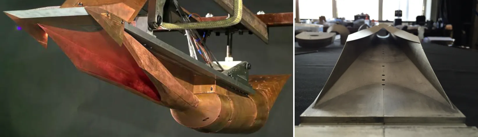
One example of present-day 3D scramjets is the Rectangular-to-Elliptical Shape Transition or REST scramjet engines. This class of engines has a rectangular capture area that helps smooth integration with the vehicle. The rectangle cross-section gradually transitions into an elliptical cross-section as it reaches the ‘rounded’ combustor.
An elliptical shape for the combustor is preferred over a rectangular shape because it offers a reduced surface area for the same amount of airflow. This aspect of a reduced surface area significantly lowers the engine drag and cooling requirement compared to a rectangle shape. Further, the elliptical shape reduces structural weight due to the inherent strength of rounded structures. Also, the curved shape eliminates low momentum corner flows, which are observed to severely limit engine performance.
Operation of a Scramjet Engine
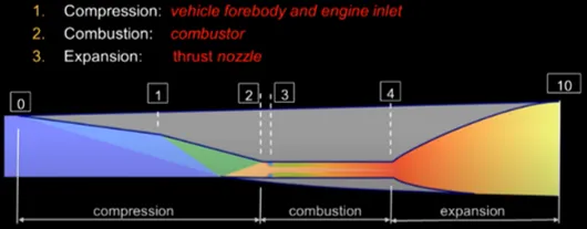
The air inside a scramjet engine passes through three distinct processes of compression, combustion, and expansion in the 3 sections: intake, combustor, and exhaust nozzle.
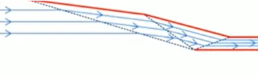
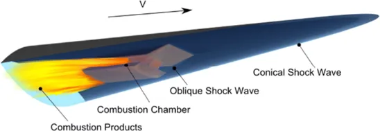
The Intake: The front part of the engine, the intake, does the job of capturing the air and compressing it. At station 0, the flow is undisturbed by the engine. As it moves towards station 1, the air starts to experience compression due to the flow contraction caused by the vehicle’s fore-body. Further compression is done by 3 shock waves generated in the intake. The flow passing through shock waves raises the pressure and temperature of the flow. Each shock wave aligns the flow to the walls of the intake, and by the time the flow leaves the inlet at station 2, it will be uniform and parallel to the walls of the combustor.
The Combustor: At the entrance to the combustor, between stations 2 and 3, a short duct called an isolator exists, which separates the inlet operations from the pressure rise in the combustor. At station 3, the fuel is injected and lighted. It burns in the hot air that has been compressed by the inlet.
The Nozzle: Lastly, the combustion products expand through the exhaust nozzle located between stations 4 and 10. It’s here the thrust for the vehicle gets generated.
Difficulties in designing scramjet engines
Although functioning-wise, a scramjet engine looks simple, designing a working engine that can sustain combustion for an extended period and survive under hypersonic conditions is a daunting challenge. Several engineering difficulties exist, starting with the challenge of mixing the fuel with air and igniting it in a high-velocity flow field within less than 1 millisecond.
The second issue is the high surface heat loads generated by hypersonic flight. These can be greater than those experienced by the space shuttle on re-entry and for longer periods. The material used to build the scramjet structure needs to be lightweight and be able to withstand elevated temperatures in excess of 2000 C. Also, thermal and structural design needs to take care of thermal expansion. Materials grow as they get heated up. So, designing a structure that does not break up as its skin heats up from room temperature to 2000 C is a major engineering challenge.
Thirdly, burning fuel in a duct can sometimes lead to choking or flow blockage. So, some mechanism needs to be built to manage it. Finally, chemical reactions can freeze in the nozzle expansion, leading to incomplete combustion.
Along with these engineering challenges, there are system-level challenges. One of the major issues is scramjets don’t work below Mach 4, so there is a need for another type of propulsion system, say, a ramjet or a rocket engine, to get it up to speed. Lastly, the nature of the scramjet operation changes considerably with the Mach number. Hence, acceleration over a large Mach range will be difficult as needed to get to space.
Parting Remarks
Given their characteristics of better fuel efficiency and high manoeuvrability, scramjets are preferred over rockets for hypersonic flights in the Earth’s atmosphere. They will likely find applications in hypersonic aeroplanes or cruisers and recoverable space launchers or accelerators. Cruisers could be a vehicle that is boosted to a certain speed by a jet-ramjet combo engine and may spend most of its time at constant velocity in the upper atmosphere. On the other hand, accelerators could probably be a part of a multi-stage rocket-scramjet combo system for low-cost reusable access to space.
Scramjets have come a long way over the last 60 years. 3D scramjet idealogy has proliferated in recent times and is been widely adopted by researchers worldwide. Also, 3D scramjets like REST have opened up the available design space, allowing possibilities for newer design variants to be tested and explored. Hopefully, this will lead to better engines with improved performance and make hypersonic flights a reality in the near future.
Further Reading
- Know your mesh for Hypersonic Intake CFD Simulations
- Spiked Blunt Bodies for Hypersonic Flights
- Engine Nacelle Aerodynamics
- Supersonic Parachutes for Reentry Vehicles
- Meshing of Rocket Engine Nozzles for CFD
- Know Your Mesh for Reentry Vehicles
References
1. “Parametric Geometry, Structured Grid Generation, and Initial Design Study for REST-Class Hypersonic Inlets“, Paul G. Ferlemann, et al., JANNAF Airbreathing Propulsion Subcommittee Meeting, La Jolla, California, 2009.
2. “Investigation of REST-class Hypersonic Inlet Designs“, Rowan J. Gollan et al., 17th AIAA International Space Planes and Hypersonic Systems and Technologies Conference, 11-14th April 2011, San Francisco, California.
3. ” “Design of three-dimensional hypersonic inlets with rectangular-to-elliptical shape transition“, Smart, M. K et al., Journal of Propulsion and Power, Vol. 15, No. 3, 1999, pp. 408–416.
4. “Free-jet Testing of a REST Scramjet at Off-Design Conditions“, Michael K Smart et al., Smart, Michael K, et al., 25th AIAA Aerodynamic Measurement Technology and Ground Testing Conference, 5-8 June 2006, San Francisco, California.
5. “Scramjet Inlets“, Professor Michael K. Smart, RTO-EN-AVT-185.
6. “Hypersonic Airbreathing Propulsion“, David M. Van Wie, et al., Johns Hopkins APL Technical Digest, Volume 26, Number 4 (2005).
7. “Hypersonic Speed Through Scramjet Technology“, Kevin Dirscherl et al., University of Colorado at Boulder, Boulder, Colorado 80302, December 17, 2015.