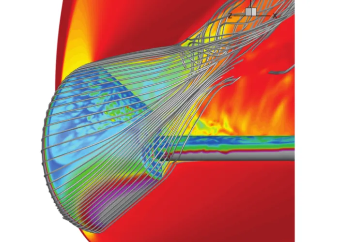
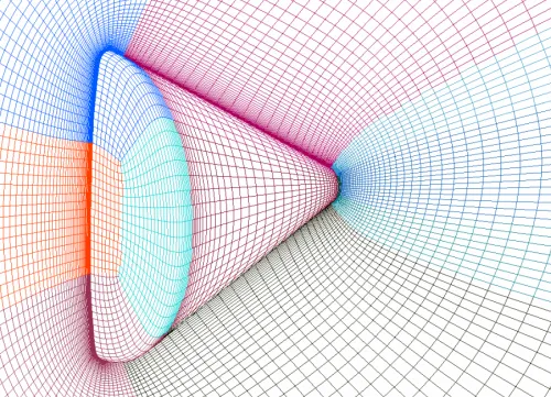
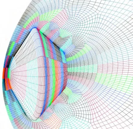
Figure 1: A typical reentry vehicles’ surface heat flux with streamlines computed using a structured multi-block grid. Image source Ref [9].
2498 words / 12 minutes read
Introduction
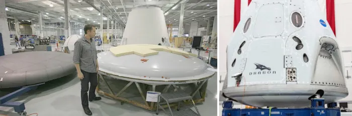
With the Falcon 9 blasting off the American astronauts in Crew Dragon to the ISS, an exciting new era of human space exploration has begun. With many private companies like Space X, Blue Origin, Rocket Lab, Sierra Nevada Corporation along with government agencies like NASA have ventured into space aggressively, vehicles like reentry capsules will become key transporting systems to bring humans safely back to Earth or even for that matter land safely on Mars.
Understanding the flow physics around these capsules through wind tunnel testing and CFD becomes a critical aspect for the optimal design of reentry vehicles for all flow conditions within the operational envelope. However, there are limitations to mimicking the hypersonic flow conditions for all possible trajectories in the wind tunnel. It is here, that CFD proves its mettle and becomes an effective tool in giving insight into the complex flow field around reentry vehicles for all flight conditions.
For accurate capturing of the flow field by CFD computations, grids play a pivotal role, especially so for such geometries with rich physics. The flow field demands tailor-made grids that are spot on to capture the multiple physics like shock, expansion fan, wake, etc. Through this article, we try to bring out the various aspects of meshing the flow field around reentry vehicles – the gridding requirements, the meshing challenges, the relation between grid and flow physics, the dos and don’t of meshing capsules, and other details.
A Glimpse of the Flow-Field Around Reentry Capsules
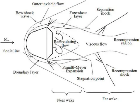
The flow field around reentry vehicles is complex and rich in physics. Figure 2 shows the schematic diagram of the flow field. The freestream fluid first encounters a strong bow shock in front of the spherical forebody and gets decelerated. At the capsule shoulder, the flow turns and expands rapidly to form an expansion fan. The flow expands further at the shoulder forming a lip shock. In the same region, the boundary layer gets detached from the surface and forms a free-shear layer, separating the inner recirculating flow region in the capsule aft region from the outer inviscid flowfield.
Further, the outer inviscid flow gets re-compressed in the capsule wake by a recompression shock wave and gets deflected back in the freestream direction. The wake downstream of the capsule classified as near wake and far wake has several flow features including, free-shear layers, flow contraction zone (the neck), and recompression shocks. The capsule experiences another stagnation point in the base region apart from the forebody stagnation region.
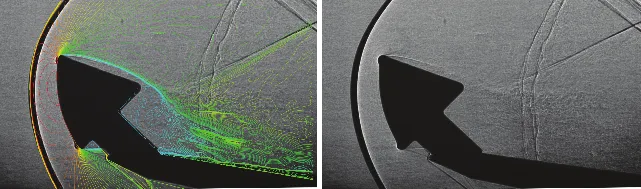
Figure 3: Apollo reentry capsule. CFD and wind tunnel shadowgraphy images. Image source Ref [4].
Figure 3 shows the comparison of the CFD prediction with the wind tunnel data for an Apollo crew capsule. The CFD results exactly mimic the wind tunnel measurements.
However, it is observed that in CFD, obtaining aerodynamic data like the forces and pressures are relatively easier than heat flux prediction by a few orders. The CFD engineer needs to pay a bit more attention to the grids, solution convergence levels, the flux scheme, and the limiter chosen for doing the computations.
Challenges in Heat Transfer Prediction
Heat-transfer calculations are sensitive to grid resolution and level of solver convergence. Gridding experiments by researchers from NASA have shown that a computational mesh and level of convergence which results in accurate surface-pressure and shear stress values do not guarantee accurate heat-transfer value. The level of grid refinement and solver convergence needed for heat-transfer prediction are much higher than that needed for aerodynamic data. Unfortunately, there is no standard ball-park number for the fall in residuals required, as the convergence level is dependent on the problem at hand and the solver used.
In addition to these findings, hypersonic computations done on axisymmetric bodies have shown that heat-transfer predictions are sensitive to the flux-splitting method and the limiter chosen. Further, a grid that is considered good for the computation of heat transfer with one particular flux-splitting scheme and limiter may not be good enough with another set of flux-splitting schemes and limiters.
Calculating the First Cell Height
Usually, for low Mach number flows, the standard practice is to calculate the first cell height based on an expected Y+ value. But, for hypersonic flows, this approach of fixed spacing does not generate optimized first-cell spacing as cell Reynolds number and the temperature jump from the wall to the first cell center decreases with an increase in boundary-layer thickness. What this implies is that the grid spacing can be relaxed progressively as we move from the forebody to the aft part of the vehicle.
We can get the value of optimum first-cell spacing for the whole configuration by conducting a systematic grid resolution study while constantly monitoring the temperature jump across the first spacing from the wall and the cell Reynolds number. Conducting such an exercise on the full-fledged 3D configuration is not recommended as it will be computationally expensive and non-feasible. Instead, performing the grid-refinement and validation exercise on a 2D axisymmetric or a simplified version of the original geometry is highly advocated. Generally, a first spacing corresponding to a Reynolds number in the range of 2-3 is used.
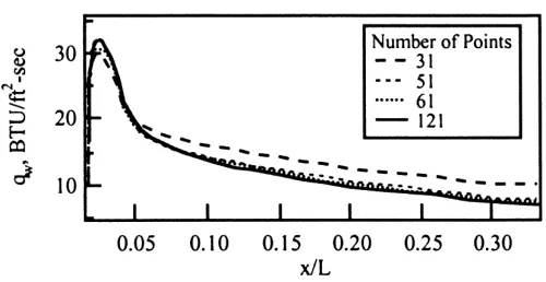
Grid Points in the Normal Direction
The number of grid points in the normal direction significantly affects the boundary layer development and wall heat flux prediction. It is observed that, if the number of points is lesser than the optimal value, there is an appreciable over-prediction of heat transfer. It is recommended to have at least 60 to 90 points in the normal direction, as more points will only make the computations expensive with very little marginal improvement in heat-transfer prediction. Figure 5 shows the gradual improvement in heat flux prediction with refinement in the normal direction.
Choosing First Cell Spacing
Along with the number of grid points in the normal direction, the first cell spacing also affects the wall heat-flux prediction significantly. Larger wall spacing, particularly in the forebody around the stagnation region triggers increased heat transfer prediction. Thus, to get a reasonably accurate solution, a wall spacing with a cell Reynolds number no more than 5, along with a smooth gradual stretching into the field based on geometric progression is strongly advocated. For turbulent flow simulations, the wall spacing should be adequate to resolve the laminar sub-layer with a y+ less than or equal to one.
However, on a cautionary note, one must be aware of the fact that the wall spacing requirement can change with a change in the angle of attack.
Point Placement in the Axial and Circumferential Directions
The sensitivity of the heat-flux prediction is observed to be small to the axial and circumferential grid resolution beyond a certain value. A grid resolution of about 160 points in the axial and circumferential direction is observed to generate grid-converged heat-flux data. Further, it is also reported that refinement in the axial direction particularly in the shoulder region and geometrical corners in the aft region, has been shown to improve the heat-flux predictions to some extent.
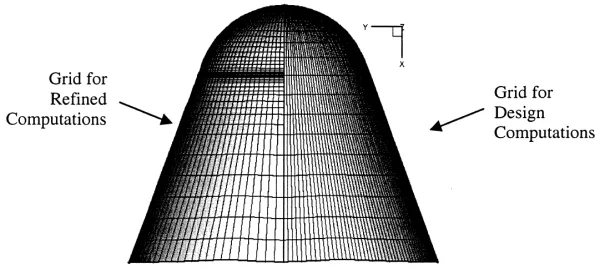
Grid Sequencing for Generating Grid-Independent Solutions
For complex-flow domains like reentry vehicles, it is essential to make use of a grid-sequencing strategy to speed up the convergence of the numerical integration process and also to show the grid independence of the numerical solutions.
Usually, about 5 grid levels are generated. The first initial grid called the coarse grid is four times coarser in all directions than the fine grid. The second grid called the medium grid is built to be two times coarser in all directions relative to the fine grid. These two grids are used to quickly establish the shock and the flow in the shock layer.
The third grid in the sequence called the fine grid has a full resolution in the normal direction and produces a reasonably accurate flow prediction. The fourth grid called the extra-fine grid has full normal and circumferential resolution but has doubly coarse grid spacing in the streamwise direction. And lastly, the fifth and final grid in the sequence called ultra-fine grid has a complete resolution in all three directions.
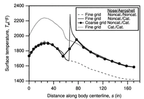
Grid Strategies for Modeling Material Maps with Interfaces
CFD computations for re-entry capsules are mainly performed with the aim of providing high-fidelity aerothermal environments for better design of the Thermal Protection System (TPS) of the vehicle. Usually, while doing CFD computations the vehicle is assumed to be made of one material that is fully catalytic in nature with constant emissivity.
What happens is that the free-stream oxygen and nitrogen molecules get split into free ions and when they reach the catalytic vehicle surface they recombine completely to form molecular oxygen and nitrogen. Heat is released due to this recombination along with the heating due to wall-bounded shear flows.
Importance of Capturing Wake Accurately
Capturing capsule wake accurately is critical for the reliable prediction of the aero-thermal data. In particular, the expansion fan around the capsule shoulder should be captured accurately as it determines the thermochemical state of the virtually frozen wake. The characteristics of the separated flow region downstream of the capsule are also determined to a large extent by the shear layer and wake compression region. Also, the recirculation zone consisting of a single vortex at a low Reynolds number and multiple counter-rotating vortices at a higher Reynolds number should be resolved appropriately.
As a gridding guideline, the grid resolution in the wake vortex and free shear layer must be of the same order as found in the wall-attached boundary layers to properly resolve the flow field gradients in these regions. Further, attention should be paid to ensure that the grid completely encloses the subsonic part of the wake, which can extend 7-8 diameters downstream.
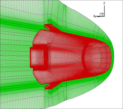
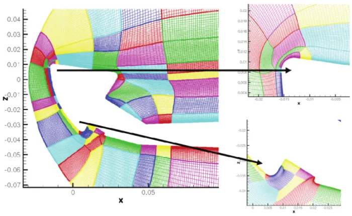
Meshing Reentry Vehicles with GridPro
GridPro comes with an array of tools ideally suited to mesh the rich flow field around reentry capsules. Individual attention can be paid to each flow physics like bow shock, shear layer, wake vortices, expansion fan, etc, and can be meshed appropriately. Such locally refined flow-aligned grids help in accurate representation of the flow field which directly aids in obtaining reliable aero-thermal data for design analysis.
The refinement regions are defined based on the flow physics in the fore-body, near wake, and far wake flow fields. These regions include the probe’s corner, expansion layer, base flow, wake, and sonic line attachment.
Trailing Thoughts
Every configuration has its own unique gridding needs. This is understandably true as the flow physics emanating from the geometry is unique to the geometric features of that configuration and the gridding requirements are also naturally different. Doing grid generation with an understanding of the flow physics is the correct way to do and make grid generation a science rather than an art.
The insight given in this article about the gridding needs for reentry vehicles relative to the associated flow physics will tremendously aid in generating the right grid for this class of problems. Tools like nesting and compact enrichment in GridPro are very effective in generating the flow physics-based aligned grids. Such grids make the CFD computations more robust, reduce the chances of code blowing up, aid in higher levels of residual convergence, and also give reliable results.
Further Reading
- Supersonic Parachutes for Reentry Vehicles
- Nesting your way to mesh Multi-Scale CFD Simulation!
- Spiked Blunt Bodies for Hypersonic Flights
References
1. “Aerothermal Analysis of the Project Fire II Afterbody Flow”, Michael Wright et al, Journal of Thermophysics and Heat Transfer, Vol. 17, No. 2, April–June 2003.
2. “Effect of geometrical parameters of reentry capsule over flowfield at high speed flow”, Advances in Aircraft and Spacecraft Science, R. C. Mehta, Vol. 4, No. 4 (2017) 487-501.
3. “Numerical Simulation of Base Pressure and Drag of Space Reentry Capsules at High Speed”, Rakhab C. Mehta, Hypersonic Vehicles – Past, Present and Future Developments. IntechOpen.
4. “Base Flow Investigation of the Apollo Command Module in the Frame of AVT-136”, Louis. M.G. Walpot et al, 48th AIAA Aerospace Sciences Meeting Including the New Horizons Forum and Aerospace Exposition, 4 – 7 January 2010, Orlando, Florida.
5. “Development of an Interactive Hypersonic Flow Solver Framework for Aerothermodynamic Analysis”, Prabhakar Subrahmanyam, Engineering Applications of Computational Fluid Mechanics Vol. 2, No. 4, pp. 436–455 (2008).
6. “Database driven planetary probe automatic geometry and grid generation tool for atmospheric entry simulations”, Periklis Papadopoulos, Prabhakar Subrahmanyam.
7. “Current grid-generation strategies and future requirements in hypersonic vehicle design, analysis and testing“, Periklis Papadopoulos et al, Applied Mathematical Modelling 23 (1999) 705-735.
8. “Aerodynamic and aerothermodynamic database of Expert capsule“, A. Schettino et al, WEST-EAST HIGH SPEED FLOW FIELD CONFERENCE, 19-22, November 2007, Moscow, Russia.
9. “Advances in Computational Fluid Dynamics Methods for Hypersonic Flows“, Graham V. Candler et al, JOURNAL OF SPACECRAFT AND ROCKETS, Vol. 52, No. 1, January–February 2015
Do you have a tutorial based on this blog would love to have look
Hi David,
You can check the GridPro video tutorial on youtube for reentry vehicles.
Here is the link:
https://youtu.be/2BPCdIXnm3U
You can also try GridPro by downloading the Free Version, by signing up here.
https://www.gridpro.com/signin/
with warm regards,
Ravindra
Hi David,
Currently, we only have one video tutorial on reentry capsules. In case we come up with a new tutorial, I will let you know.
with warm regards,
Ravindra
Ravindra, thank you, will do. Thanks again for your help. I have started reading the reference material from the GridPro Blog,…if you have any suggestion on other tutorials pertaining to human reentry I’d greatly appreciate the heads up.