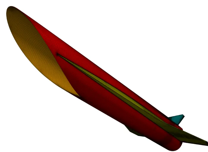
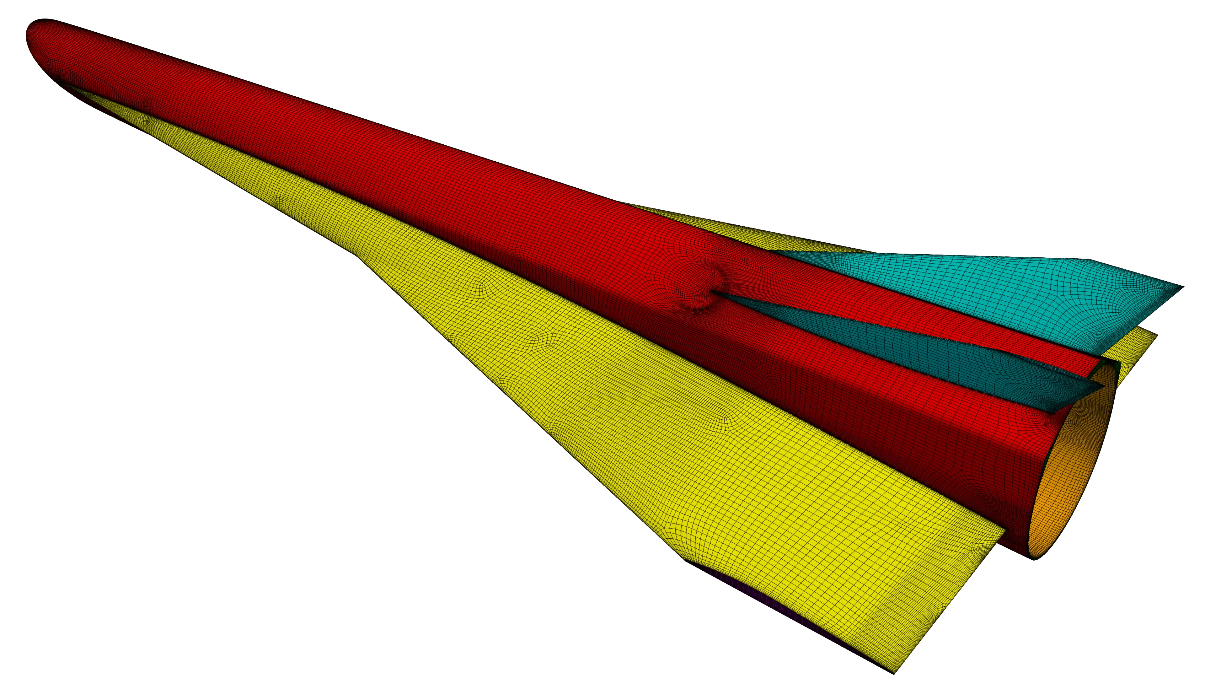
Figure 1: Hexahedral mesh for HiFire6 vehicle with Busemann hypersonic intake.
1200 words / 6 minutes read
Hypersonic flow phenomena, such as shock waves, shock-boundary layer interactions, and laminar to turbulent transitions, necessitate flow-aligned, high-resolution hexahedral meshes. These meshes effectively discretize the flow physics regions, enabling accurate prediction of their impact on the flow.
Introduction
In light of successful scramjet-powered hypersonic flight tests conducted by numerous countries, the pressure is mounting for other nations to keep up with this technology. Extensive testing and computational fluid dynamics (CFD) simulations are underway to develop a scramjet design capable of withstanding the demanding conditions of hypersonic flight.
As an effective and efficient design tool, CFD plays a pivotal role in rapidly designing and optimizing various parametric scramjet configurations. However, simulating these extreme flow fields using CFD is a formidable challenge, and proper meshing is of utmost importance.
The meshing requirements for CFD of hypersonic flows in intakes differ significantly from those for low Mach number flows. High-speed flows involve elevated temperatures and interactions between shockwaves and boundary layers, which were previously negligible. Boundary layers are particularly critical as they experience high rates of heat transfer. Furthermore, the transition of the boundary layer from laminar to turbulent flow is a complex phenomenon that is challenging to capture and simulate accurately. Nonetheless, this transition is of paramount importance, as it has a profound impact on flow behaviour.
What Should the Mesh Capture?
Change in the flow field demands a change in meshing requirements. As one may expect, the boundary layer should have a high resolution to capture the velocity boundary layer and the enthalpy boundary layer. Next, the shocks must also be captured precisely since the flow turns through the shock wave in hypersonic flows. But more importantly, shocks have extremely strong gradients, which can lead to large errors if not resolved accurately.
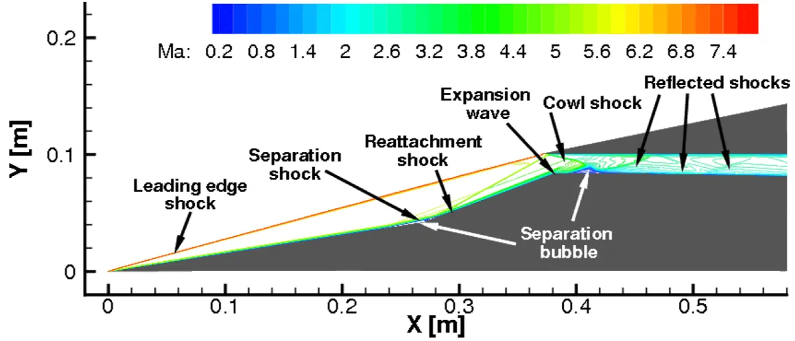
Multiple shocks and boundary layer interactions happen in hypersonic intake flows at different locations. If these effects are not resolved precisely, it is impossible to predict whether the hypersonic engine works effectively or not. To summarise, we must deal with multiple effects with different strength levels. The gridding system we adopt should create a grid that adequately resolves all effects with sufficient precision to achieve the needed level of solution reliability.
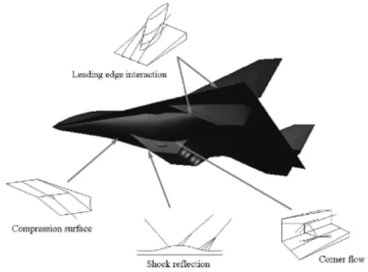
Other regions of concern in scramjet are the inlet leading edge, injector and cavity. Not only does the mesh topology have to be appropriately structured around these regions, but it must also align with the surfaces as best as possible to avoid introducing unnecessary skewing and warpage.
Boundary Layer Capturing
The boundary layer, a home for laminar to turbulent transitions and shock-induced boundary layer separation, must be properly resolved. Usually, structured meshes are preferred. Even the hybrid unstructured approach adopts finely resolved stacked prism or hexahedral cells in viscous padding.
This is necessary because resolving the boundary layer close to the wall aids in accurately representing its profile, leading to correct predictions of wall shear stress, surface pressure and the effect of adverse pressure gradients and forces.
Further, at hypersonic speeds, the transition of laminar to turbulent boundary layer inside the boundary layer significantly influences aircraft aerodynamic characteristics. It affects the thermal processes, the drag coefficient and the vehicle lift-to-drag ratio. Hence, paying attention to how well the cells are arranged in the boundary layer padding is critically essential.
Shock Wave Boundary Layer Interactions (SWBLI)
Another important aspect of the proper resolution of the boundary layer is how it helps predict shock-induced flow separation. Shock wave interaction with a turbulent boundary layer generates significant undesirable changes in local flow properties, such as increased drag rise, large-scale flow separation, adverse aerodynamic loading and heating, shock unsteadiness and poor engine inlet performance.

Unsteadiness induces substantial variations in pressure and shear stress, leading to flutter that impacts the integrity of aircraft components. Additionally, the operational efficiency of engines can be considerably compromised if the shock-wave-induced boundary layers separation deviates from the anticipated location. If the computational grid fails to accurately represent the interaction between shock waves and boundary layers due to inadequate resolution or improper cell placement, the obtained results from CFD will lack practical utility or advantages. This underscores the critical significance of well-designed grids in the context of hypersonic flows.
Shock Capturing
Ideally, grid lines need to be aligned to the shock shape. For this, hexahedral meshes are better suited. They can be tailored to the shock pattern and made finer in the direction normal to the shock or adaptively refined. This brings the captured shock thickness closer to its physical value and improves the solution quality by aligning the faces of the control volumes with the shock front. Shock-aligned grids reduce the numerical errors induced by the captured shock waves, thereby significantly enhancing the computed solution quality in the entire region downstream of the shock.
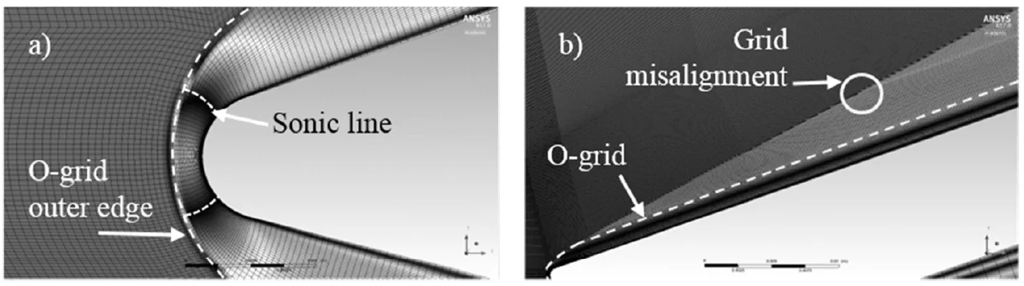
This grid alignment is necessary for both oblique and normal bow shock. Grid studies have shown that solver convergence is extremely sensitive to the shape of the O-grid at the stagnation point. Matching the edge of the O-grid with the curved standing shock and maintaining cell orthogonality at the walls was necessary to get good convergence.
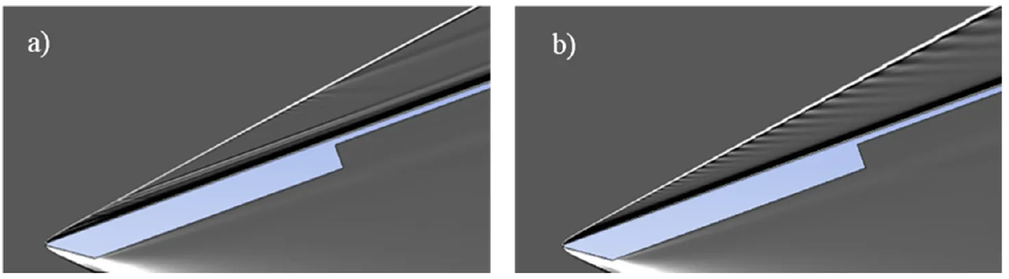
Also, grid misalignment is observed to generate non-physical waves, as shown in Figure 7. For CFD solvers with low numerical dissipation, a strong shock generates spurious waves when it goes through a ‘cell step’ or moves from one cell to another. Such numerical artefacts can be avoided, or at least the strength of the spurious waves can be minimized by reducing the cell growth ratio and cell misalignment w.r.t the shock shape.
Aspects to Consider While Doing Grid Refinement
A sparser grid density may suffice in areas where flow is uniform and surfaces have slight curvatures. Nevertheless, it becomes necessary to employ grid clustering and increase the resolution in regions characterized by abrupt flow gradients, geometric or topological variations, regions accommodating critical flow phenomena (such as near walls, shear and boundary layers, shock interactions), geometric cavities, injectors, and other solid structures. The appropriate refinement of these regions holds significance as it contributes to enhancing the efficacy of numerical schemes and models at both local and global levels. Consequently, this refinement leads to the generation of more precise and reliable results.
When employing a solution-based grid adaptation approach, the selection of an appropriate refinement ratio and initial grid density becomes crucial. If the refinement ratio is too low, it may be inefficient and ineffective. This is due to the limited coverage of the asymptotic region, which may not be sufficient to accurately determine the convergence behaviour. Additionally, it may necessitate multiple flow solutions before reaching a valid conclusion.
Another aspect which needs due attention while making grid adaptation is the initial grid employed. The initial grid should possess a sufficient level of resolution. Employing a low initial grid density can lead to inaccurate simulation results and unsatisfactory flow field solutions. On the other hand, an excessively refined initial grid may not be feasible for high-fidelity studies involving viscous, turbulent or fully reacting flows. This is because the initial cell density may already be too high, making creating subsequent grids with even higher densities impractical.
Conclusion
Grid accuracy plays a critical role in the reliability and precision of hypersonic CFD simulations, as it directly influences the computed flow field. Given the high velocities involved, errors introduced upstream can rapidly amplify downstream.
Consequently, it is imperative to employ a meticulous grid or topology design to achieve suitable cell discretization and blocking structures. Factors such as grid resolution, grid clustering, cell shape, and cell size distribution must be thoroughly evaluated and selected both locally and across the entire domain. This careful assessment is essential for preventing the introduction of errors and inaccuracies into the computed results through numerical artefacts and uncaptured phenomena.
For more insights into high-resolution, flow-aligned meshing solutions tailored for hypersonic applications, explore GridPro’s capabilities here, which highlight its precision benefits for aerospace CFD.
References
1.“Experimental Study of Hypersonic Fluid-Structure Interaction with Shock Impingement on a Cantilevered Plate”, Gaetano M D Currao, PhD Thesis, UNSW AUSTRALIA, March 2018.
2.“Investigation of “6X” Scramjet Inlet Configurations”, Stephen J. Alter, NASA/TM–2012–217761, September 2012.
3.“Numerical Simulation of Hypersonic Air Intake Flow in Scramjet Propulsion Using a Mesh-Adaptive Approach”, Sarah Frauholz, et al, AIAA Conference Paper · September 2012.
4.“Parametric Geometry, Structured Grid Generation, and Initial Design Study for REST-Class Hypersonic Inlets”, Paul G. Ferlemann et al.
5.“Numerical Simulation of Hypersonic Air Intake Flow in Scramjet Propulsion”, Sarah Frauholz et al, 5TH EUROPEAN CONFERENCE FOR AERONAUTICS AND SPACE SCIENCES (EUCASS), July 2013.
6.”Computational Prediction of NASA Langley HYMETS Arc Jet Flow with KATS”, Umran Duzel,AIAA conference paper, Jan 2018.
7.“Numerical simulations of the shock wave-boundary layer interactions”, Ismaïl Ben Hassan Saïdi, HAL Id: tel-02410034, 13 Dec 2019.
8.“The Role of Mesh Generation, Adaptation, and Refinement on the Computation of Flows Featuring Strong Shocks”, Aldo Bonfiglioli et al, Hindawi Publishing Corporation Modelling and Simulation in Engineering, Volume 2012, Article ID 631276.
9.”Numerical Investigation of Compressible Turbulent Boundary Layer Over Expansion Corner“, Tue T.Q. Nguyen et al., AIAA Conference Paper, October 2009.