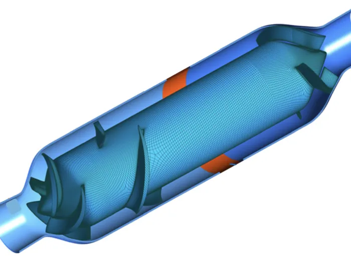
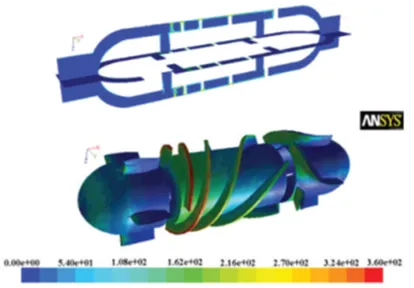
Figure 1: Structured multiblock grid for mixed-flow blood pumps. Image source Ref [8].
2400 words / 12 minutes read
Introduction
The human heart beating more than a hundred thousand times a day and roughly 35 million times a year, is the most vital organ. Sadly, we take the health of our hearts for granted. More than one million people worldwide have critical heart conditions which despite optimal medical and surgical treatments continue to deteriorate and for them, a heart transplant is the only option for survival. Unfortunately, the number of donor hearts available is very limited. Statistical reports show that in the US alone, annually only around 3000 patients out of 35,000 get a total heart transplant, while the rest are put on the waiting list.
In addition to limited donor heart availability, there are other constraints like prohibitively high cost and limited expertise to handle heart transplants. The woes don’t end here. Even after a heart transplant, the patient may still die due to operative complications, trauma, and organ rejection. The need for immunosuppression for long period makes heart transplants a less appealing option.
These inherent issues with heart transplants have led to the development of Total Artificial Heart (TAH) since the 1960s and the developmental efforts continue to this day. The TAH is perceived as an option to keep the patient alive while waiting for a donor’s heart. Unfortunately, even though TAH got approved in the 90s, they are still in clinical trials. Their bulky size and complexity make them less attractive and have made many researchers go for smaller and simpler pumping mechanisms which rather than replacing the patient’s heart, try to assist it. One such biomechanical device to support blood circulation in patients is ventricular assist devices (VADs).
Video 1: How VADs work.
Ventricular Assist Devices
VADs are electromechanical pumps designed to support or replace the role of one or more chambers of a failing heart. Consisting of a blood pump, a power unit, and a control unit, it tries to reduce the heart’s workload by aiding in blood circulation and maintenance of adequate blo
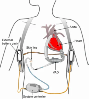
od pressure. Long-term use of VADs called bridge-to-transplant helps to sustain the patient while waiting for a heart transplant outside the hospital. For patients who are not candidates for transplant, VADs are used as destination therapy for providing long-term support.
Depending on the need, VADs can be implanted to assist the left ventricle (LVAD) or the right ventricle (RVAD), or even both (Bi-VAD). These VADs need to be small and easily implantable not only in heart failure adult patients but also in pediatric patients with congenital or acquired ventricular dysfunction.
Blood pumps, the principal component of VADs are a challenge to design. They are expected to operate over a wide range of pressure heads and flow rates while inflicting minimal damage to blood cells. Hemolysis (i.e the release of hemoglobin from red blood cells) beyond a certain level and thrombosis (i.e blood clotting) are the two major life-threatening factors VAD-dependent patients need to deal with.
Pulsatile or Continuous Flow Pumps Which is Better?
Blood pumped by a human heart is pulsatile in nature. So naturally, in the initial stages of blood pump development, researchers considered developing positive displacement pumps to deliver pulsatile flow. Pulsatile blood flow has some inherent benefits. They tend to clear away cell agglomerations at flow stagnation points thereby reducing the occurrence of blood clotting, stroke, and other complications.
However, studies have shown that pulsatile flow is not a ‘must’ requirement and continuous flow as well serves the purpose of supplying blood to all corners of the body for several years. The rationalization is that blood by the time it reaches the capillaries, the pulsatile nature would have got dampened out and the flow would effectively be continuous. Also, pulsatile pumps have shown to have worse hemolysis than continuous flow pumps because of the presence of valves in the flow path.
Though the impact of removing the pulsatility of the blood flow is debatable, continuous flow pumps especially axial pumps score over pulsatile pumps w.r.t smaller size, simplicity with fewer moving parts, ease of implantation, and lower power consumption. On the other hand, displacement pulsatile pumps due to their large size make them difficult to implant, while their thick percutaneous drivelines and noisy operation make them uncomfortable to wear. Other side effects include bleeding, infections, and thrombo-embolic occurrences. Due to these reasons, continuous flow pumps are favored over pulsatile pumps.
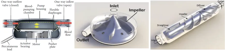
Figure 3 shows the most commonly used continuous flow pumps namely, centrifugal and axial flow pumps. Centrifugal pumps produce higher pressure at lower flow rates while axial pumps generate a higher flow rate with lower pressure rises. Axial pumps rotating relatively faster are smaller, lighter, and consume less power than centrifugal pumps. Hence, axial pumps are more attractive as they can be implanted more easily and are better suited for pediatric usage.
Ironically, though at one hand these blood pumps help in prolonging the life of patients, they also, on the other hand, bring in new complications that lessen the patient’s life span.
Blood Damage due to VADs
Usage of VADs has some inherent adverse effects in the form of thrombus formation, hemolysis, and Acquired von Willebrand Syndrome. These side-effects of VADs are directly correlated to the shear stress, strain rate, and turbulent energy dissipation in the bloodstream.
Hemolysis referred to the process of premature destruction of red blood cells and the release of hemoglobin into the plasma when blood is subjected to high shear stress over a certain length of time. This happens all the time in blood pumps. As impellers rotate at high speed to maintain the required blood pressure, high-velocity gradients are generated in the fluid, which results in increased shear stress, and this ultimately leads to hemolysis. This problem is more acute in axial pumps than centrifugal pumps due to higher rotational speed.
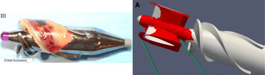
On the other hand, thrombosis refers to the process of clotting of blood cells due to flow stagnation, abnormalities in the blood flow pattern, or on walls of the flow passage. They are initiated by the activation of platelets and subsequent adherence of platelets and leukocytes to the tissues of the native blood vessels or to a foreign substance like a blood pump. Though it is largely a fluid dynamics effect, it is also dependent on the material the blood is contacting with, especially artificial implant organs like blood pumps.
Activated platelets and thrombus may remain suspended in the bloodstream and they may adhere to biological surfaces further downstream or club with one another to form blood-borne emboli. These emboli travel in the flow passage until they clog small arteries or settle down in tissues or organs. This is dangerous as clogging of critical organs like lungs could be potentially fatal.
These life-threatening blood damages are the greatest challenge in the design of mechanical blood pumps.
Challenges in Designing VADs
The use of VADS is not without risks. The unphysiological conditions they produce in the circulatory system can cause infection, inflammation, and thromboembolism. Emboli when carried to the brain, kidney, liver, and heart lead to strokes, impairment of kidney and liver function, and heart attacks. To avoid or reduce thrombosis due to VADs, patients are required to take anti-coagulation medication which in turn
The other issue pertains to device size. Though the present 3rd generation of VAD designs is smaller than their predecessors, they are still bulky and uncomfortable to wear especially for small children. While implantable devices demand a physical body of a certain size, extracorporeal devices are uncomfortable and worrisome for patients. Device size minimization is necessary to reduce the trauma of implantation and the risk of infection.
One possible solution is the reduction in power requirements. This not only will decrease the device size, but also problems associated with a totally implantable system as well.
While miniaturization of the pump is the need of the hour, doing so will result in reduced clearance gaps along with an increase in speed, which results in increasing hemolysis and thrombosis. If these conflicting issues can be addressed, VADs can greatly enhance the longevity and quality of life of heart failure patients.
So, while miniaturization is a challenge, ways to reduce infection is also a high priority requirement. For this, one possible way is to find materials that are biocompatible and also design surface textures that encourage the natural growth of cells to reduce the risk of thrombosis.
If we look at these medical issues arising due to pump usage, from a fluid dynamics perspective, it all boils down to pressure and friction inside the pump leading to damaged blood cells and the generation of stagnation regions that makes blood gather and clot. Introducing subtle design variations and optimizing the pump components such as impeller and casing geometries could minimize these fluid dynamic issues. For example, by improving the blood flow pattern by removing stagnant regions, the tendency of blood to clot can be reduced considerably.
In a nutshell, blood pump designers need to pay attention to eliminate regions of high shear stress, stagnation, or recirculation spots and avoid materials with low hemocompatibility properties to overcome the adverse effects and make VADs more viable.
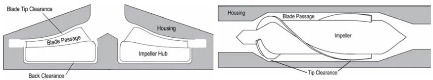
Clearance Gap and Blood Damage
One design parameter in blood pumps that has a significant impact on the pump’s hydrodynamic performance and the extent of blood damage is the gap clearance. They are the epicenter of high shear stress directly influencing the degree of hemolysis. Before we get into the details, let’s get a birds-eye view of the flow path in pumps.
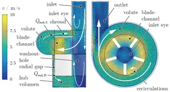
Along with the main flow, leakage flow develops as the fluid tries to pass through the shroud and the hub clearance gap around the impeller. In general, only 60% of the flow passing through the blade exits the pump, while the remaining 40% stays back as recirculating leakage flow. This leakage flow while reducing the hydraulic efficiency, increases the washouts in clearance gaps around the impeller, thereby aiding in reducing residence time and cell destruction. Interestingly, nearly 40% of the leakage flow recirculates through the radial and hub clearance gap while the rest 60% recirculates through the shroud clearance gap to the blade impeller eye.
Hemolysis can be further reduced by increasing the inlet nozzle fillet radius. With this change smoother recombination of the leakage flow across the shroud gap with the incoming flow set in. This leads to a better shear stress distribution across the housing lid. 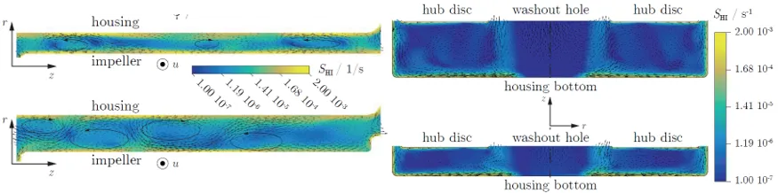
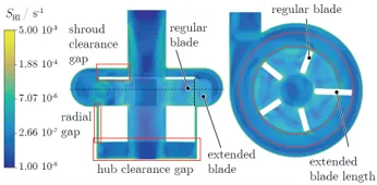
Figure 9: a. Distribution of source term S_HI in the radial clearance gap for two pump variations. b. Distribution of source term S_HI in the hub clearance gap for two pump variations. Image source Ref [5].
CFD Based VAD Design
The design objectives for VADs are optimal hydraulic performance and good hemocompatibility. Apart from this, the development of blood pumps needs to satisfy many general requirements such as affordability, easy to control, lower traumatic behaviour, reliability, safe implantability, and compatibility with patients with differing physiques.
With such a diverse requirement, often conflicting with one another, it is very challenging to design blood pumps as it results in one design criterion being optimized to the detriment of another.
CFD has become a very handy and effective tool in the optimal design of blood pumps. It is widely used as a convenient and efficient tool for analyzing pump performance and flow patterns. They provide valuable information about the flow field like velocities, pressure and shear stress, location and size of recirculation and stagnation zones, and exposure time of RBCs to stresses, which are further used to estimate the extent of hemolysis and thrombus formation.
The challenge in CFD modeling of blood pumps is that blood is a multi-component fluid with non-linear behaviour. Blood rheology is complicated and many models have been developed to describe it on different scales, from microscale models incorporating the time history of agglomerates to Eulerian models of shear-dependent viscosity. Also, the use of non-Newtonian models of blood rheology may lead to better predictions of the continuum properties of the flow field, as one study revealed treating blood as Newtonian will lead to underestimation of hemolysis levels.
In CFD prediction of blood pump flow field, blood behaviour models, blood damage models are combined with pump CFD models to understand pump performance and estimation of blood damage.
Even though many blood damage models have been proposed based on empirical data, there is no widely accepted approach for accurate prediction of the extent of hemolysis and thrombosis. Some of the popular hemolysis models include finding RBC damage based on different fluid stress-exposure time power-law models, strain-based cell models, and energy dissipation models.
Unfortunately, due to this lack of a universally acceptable model, CFD prediction often overestimates the cell damage and the prediction tends to be less reliable. Also, hemolysis models are not standard in commercial software and it is usually left for the users to implement them. This is because there is a lack of confidence in the currently existing hemolysis models.
The flow regime in the VADs also poses a challenge in making CFD predictions. This is because VADs operate in a flow regime that sits in the transitional region at the boundary of laminar and turbulent flow. This makes them tricky to predict using CFD because traditional turbulence models are developed to predict high Reynolds number flows. This puts the researcher in a no man’s land as he has to either choose the traditional model or to treat the flow as laminar when both are not true. Both approaches have been used and the results are debatable.
Parting Thoughts
All currently available blood pumps have limited design life due to mechanical wear and tear or due to thrombus formation within the device leading to device failure. Currently, most long-duration pumps come in the range of 5-10 years. Efforts are underway in academic institutions and industry to increase their usage life, make them more biocompatible, improve their performance and reliability to the level of using them as a permanent implant. And CFD on its part is playing a lead role in making the medical community meet these objectives.
Further Reading
References
1. “Elimination of Adverse Leakage Flow in a Miniature Pediatric Centrifugal Blood Pump by Computational Fluid Dynamics–Based Design Optimization”, Jingchun Wu et al, ASAIO Journal 2005.
2. “Blood Flow Through Channels and Clearances in Implantable Pumps”, Steven W. Day, Proceedings of ASME ICNMM2007 5th International Conference on Nanochannels, Microchannels and Minichannels June 18-20, 2007, Puebla, Mexico.
3. “Axial Flow Artificial Heart Blood Pumps: A Brief Review”, Dhyaa Kafagy et al, Trends Biomater. Artif. Organs, 27(3), 124-130 (2013).
4. “The Use of Computational Fluid Dynamics in the Development of Ventricular Assist Devices”, Katharine H. Fraser et al, Med Eng Phys. 2011 April ; 33(3): 263–280.
5. “CFD Assisted Evaluation of in Vitro Experiments on Bearingless Blood Pumps”, Pascal Puentener et al, IEEE TRANSACTIONS ON BIOMEDICAL ENGINEERING, 2020.
6. “Comparison and Experimental Validation of Fluid Dynamic Numerical Models for a Clinical Ventricular Assist Device”, Jiafeng Zhang et al, 2013, Artificial Organs, International Center for Artificial Organs and Transplantation and Wiley Periodicals, Inc.
7. “Computational Fluid Dynamics Analysis of Blade Tip Clearances on Hemodynamic Performance and Blood Damage in a Centrifugal Ventricular Assist Device”, Jingchun Wu et al, Artif Organs. 2010 May ; 34(5): 402–411.
8. “Computational Fluid Dynamics-Based Design Optimization for an Implantable Miniature Maglev Pediatric Ventricular Assist Device”, Jingchun Wu et al, Journal of Fluids Engineering, APRIL 2012, Vol. 134 / 041101-1.
9. “Structural Design and Numerical Simulation of an Implantable Axial Blood Pump”, Weibo Yang et al, Journal of Biomedical Science, Open Acc J Bio Sci. November – 1(3): 83-92.
10. “A Review of Computational Fluid Dynamics Analysis of Blood Pumps”, M. BEHBAHANI et al, European Journal of Applied Mathematics 20 (2009) 363–397 1.
11. “FDA Benchmark Medical Device Flow Models for CFD Validation”, Richard A. Malinaus kas et al, ASAIO Journal 2017, Biomedical Engineering.
12. “New Insights in the Diagnosis and Treatment of Heart Failure“, Giulio Agnetti et al, Hindawi Publishing Corporation BioMed Research International, Volume 2015, Article ID 265260, 16 pages.
13. “Classification of the Frequency, Severity, and Propagation of Thrombi in the HeartMate II Left Ventricular Assist Device“, Grant Rowlands et al, ASAIO Journal 2020.
14. “Numerical Simulation of the Flow in a Micro-Axial Blood Pump“, Michael Triep et al, PAMM · Proc. Appl. Math. Mech. 6, 145–146 (2006).