
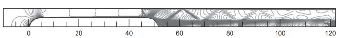
Figure 1: Structured multiblock grid for a conceptual hyperloop.
2110 words / 11 minutes read
Introduction
When Elon Musk of Tesla and Space X fame, released a white paper on the futuristic ‘Hyperloop’ concept in 2013, it was heralded as a transportation revolution. Pitched as the fifth mode of transport after road, water, rail, and air travel, Hyperloop has spurred a lot of public interest and also caught the imagination of many engineers and private companies. Though the concept of near-vacuum tube transportation has been for decades, Musk went one step ahead with his vision of a pneumatic, tube-based transportation system that could transport people at speeds near to the speed of sound.
The fundamental idea of traveling in tubes is not new. Thoughts of tube travel can be traced back to a couple of centuries ago, including Medhurst’s 1812 work on a tube-based rapid conveyance of goods and passengers and in the 1895 short story ‘An Express of the Future’ by Michel Verne, where he visioned people traveling using submarine tubes.
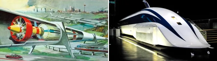
The recent drive to look for technologies beyond the conventional high-speed rail is because of the inherent limitations of this old system. Though speeds as high as 540 km/hr have been reached, the occurrence of strong vibration puts a practical limit on the rail system. Concepts like hover trains using a cushion of air to lift the train were proposed in the 1930s with the aim to avoid rolling resistance and decrease infrastructure costs by eliminating the need for rails. However, improvements in magnets in the 1970s paved the way for MagLev technology, where lift and propulsion became possible using magnets. Even though MagLev eliminated the rolling resistance, the aerodynamic drag barrier still exists. This problem compelled the Engineers and innovators to look towards train concepts in vacuum tubes. Hyperloop is an off-shoot of this line of thought.
Video 1: Hyperloop concept.
So what is Hyperloop?
Drawing inspiration from hovertrain, MagLevs, and vacuum train, Hyperloop is a ground-based high-speed transportation concept hypothesized to drastically reduce the travel time over medium-range distances. Here the passenger capsule is stated to travels at 1220 km/hr in a partially evacuated tube propelled and levitated using a combination of air bearings and electro-magnets.
It is pitched to be a faster, cheaper alternative to high-speed rails and traditional short-haul aircraft. For instance, the time taken to cover distances like Boston to New York or Los Angeles to San Francisco by aircraft is quite low. However, the overall end-to-end travel time is high when you include the inescapable inefficiencies in air travel like arriving at the airport early, runway taxiing, climb, descent, holding patterns, etc. A preliminary study on Hyperloop on the Helsinki-Stockholm corridor estimates that Hyperloop could cut down the end-to-end travel time by 75 percent.
Working mechanism-
In Hyperloop, the pods move in a low-pressure (~ 0.1 to 1% of normal atmospheric pressure) tube, levitated by air cushion or magnetism. The use of wheels at high speeds is not advisable as they generate high rolling friction and large centripetal forces. So, as a solution, an air bearing system is proposed, wherein the pod floats on a thin film of compressed air. Though considered as a low-cost option, the design proposal of a 1mm clearance gap between the tube and the bearing makes many researchers conclude that the air-bearing system is the ‘most difficult part of the Hyperloop’. As a consequence, efforts of late are more focussed on magnetic levitation, a well-proven concept, which has the potential to be more tightly coupled with the electromagnetic propulsion system for even higher efficiencies.
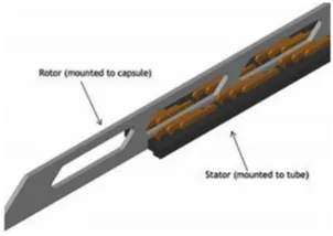
The advantage with this system is that much of the heavy components like energy storage systems will be placed outside the vehicle, on the track-side, while the pod has to carry only a rotor. This substantially reduces the weight and mechanical complexity of the pods and makes propulsion, very efficient. Further, the same linear induction motor can be used for braking the pod to a halt at the end of the journey and recover back substantial amounts of energy.
In a way, Hyperloop makes use of a fusion of technologies from both aerospace and high-speed-rail applications. Just like aircraft pulling up to high altitudes to cruise in a low-pressure zone to minimize aerodynamic drag, Hyperloop makes use of evacuated tubes to achieve lower drag at ground level. Transonic pod speed, low-density air-path, and aerodynamically driven design give Hyperloop qualities more similar to an aircraft than a train. However, unlike aircraft, Hyperloop traveling in a tube can operate independently of the fluctuations in weather conditions. Lastly, by making use of newer and cleaner propulsion technologies, they are more efficient and environmentally friendly.
Just like in aircraft, vehicle aerodynamics plays a critical role in pod design. To achieve maximum possible speed with minimal electrical energy consumption it is essential to optimize the pod shape, considering the pod aerodynamics. The following sections, cover the pod aerodynamics and design aspects in detail.
Aerodynamic disturbances:
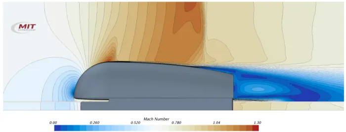
In conventional modes of transport like trains, buses, and cars, the vehicle velocity is well below the sonic velocity, and flow phenomena like shock waves are not generated and hence shock waves are not considered as an influential factor during the design stage. However, hyperloop pods which are intended to travel at transonic speeds, are very likely to generate shock waves, characterized by a sudden increase in pressure, temperature, and density. The onset of shock waves results in the generation of a new type of drag called wave drag. Furthermore, they trigger boundary layer separation, which further increases the aerodynamic drag. Hence, it is essential to design the Hyperloop to avoid shock waves at all cost.
So, what is Kantrowitz limits? Let’s try to understand this along with another important concept called blockage ratio before we delve further into the subject.
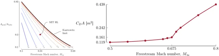
A combination of blockage ratio, velocity, and tube pressure determines whether the Kantrowitz limit is reached or not. Maximum pod operating speed is inversely proportional to tube pressure and blockage ratio. For enhanced aerodynamic efficiency, the blockage ratio and tube pressure should be minimized. Any spot on the right side of the dark line in figure 6a indicates reaching the Kantrowitz limit. What this means is that for speeds close to Mach number 1, a very low blockage ratio is required to prevent reaching the Kantrowitz limit. In other words, for a reasonably sized pod, Kantrowitz limit puts an upper limit to the pod speed without an additional increase in drag.
Fortunately, there are solutions to this problem. The Kantrowitz limit can be avoided and two approaches are commonly advocated. According to the first method, the blockage ratio can be increased, which will make relatively more air pass around the pod at a lower velocity, thereby avoiding choking and its detrimental effects. In the second approach, we can use a compressor to suck in the air at the pod front and partly feed it for air cushioning and eject out the rest through the back-end nozzle, generating a small amount of thrust.
However, both options have their limitations and drawback. Increasing blockage ratio means, either, a reduction in pod cross-sectional area resulting in a decrease of payload, or, an increase in tube construction costs. On the other hand, the need for a transonic compressor at a low Reynolds number with a high compression ratio demands a large research and development effort, as they are currently not in use in any aerospace applications.
Aspects of Pod Design
While parameters like pod speed, tube pressure, and blockage ratio are important to the overall drag of the entire Hyperloop system, the pod shape in itself has a significant impact on aerodynamic performance. Geometric design variables like pod length, height, width, 3D shape, frontal area, etc need to be optimized with the objective of minimizing the drag force. In this section, we will discuss some of these design alterations and their effect on pod aerodynamics.
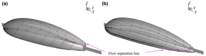
Hyperloop pods travel in a very unconventional flow regime of high Mach number, relatively low Reynolds number, and low air density. Because of this, the laminar to turbulent transition and boundary layer flow separation is very likely to happen leading to a significant increase in aerodynamic drag. Therefore, it is essential to design the pods aerodynamically to lower the boundary layer separation to the extent possible to attain lower drag. One of the ways is to strategize the location where laminar to turbulent transition and turbulent flow separation takes place by manipulating the pod surface contour.
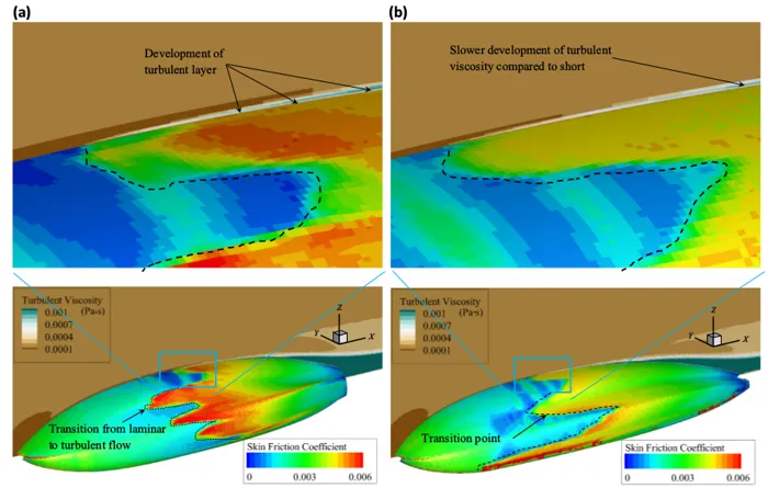
At low Reynolds number, laminar boundary layer separation gets triggered very easily even at a very low adverse pressure gradient. As a consequence, even though the skin-friction drag is low due to prevailing laminar flow on the surface, pressure drag shoots up due to a large wake. So, laminar separation is something that should be prevented to have a lower total drag.
On the other hand, turbulent boundary layers can handle larger pressure gradients. So in order to take advantage of this flow aspect, the pods are aerodynamically designed to make the laminar to turbulent transition close towards the front of the pod before flow separation happens.
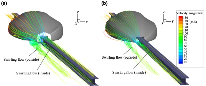
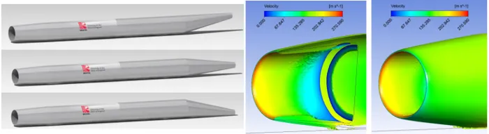
For nacelles, a divergent nozzle section is preferred as it helps to slow down the flow before entering the compressor. Moreover, accurate design of nacelle tip radius and angle is very essential since, with an increase in pod speed, the flow could likely become supersonic locally, which could prove to be problematic for the axial compressor, overall aerodynamics, pod stability, and structural integrity due to undesirable vibration. Accurate optimization in this region is critically important.
Video 2: Structured multi-block meshing of Hyperloop prototype.
The overall design of a hyperloop system doesn’t end at just considering the blockage ratio, pressure, speed, and pod shape. All these highly interdependent parameters ultimately influence the economic parameters like total annual energy cost, construction cost, and operating costs. Trade studies help to understand this relation and the sensitivity of the Hyperloop to key design parameters.
Trade Studies
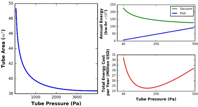
Pressure trades- Figure 11 shows the tube area as a function of pressure. As pressure increases, the tube area decreases until leveling off around 3500 Pa. Analysis of the net energy needed for maintaining tube pressure shows that it is of the same order of magnitude as the energy required to propel the pod. In fact, the two systems have opposite sensitivities to tube pressure. If the tube pressure is reduced, the energy needed to push the pod drops, but that needed to maintain tube pressure goes up. It is possible to arrive at an optimal operating pressure, which is largely dependent on the leakage rate. The higher the leakage rate higher will be the optimal operating pressure.
Capacity trades- In the original Musk’s Hyperloop proposal, the pod was suggested to carry 28 passengers only at a given time. However, analysis has shown that the net energy usage is relatively insensitive to pod length. This means the length of the pod can be increased or decreased to vary the capacity, depending upon the market demand without any increase in operating cost.
https://youtu.be/xKvbSboQ5_g
Video 3: The first-ever hyperloop passenger test by Virgin Hyperloop.
Conclusion
Hyperloops bring in many benefits. Apart from the obvious travel time reduction, it offers cheaper and large-scale commercial travel, economical energy consumption, lower noise pollution, and reduced carbon emissions. Further, as an offshoot benefit, it frees up the airspace, reduces congestion and travel times of flights that are ideally suited for long-distance, inter-continental travel.
When Elon Musk proposed the Hyperloop concept 8 years ago, people said that this is not possible, this is not going to happen. There are still many technical challenges to overcome, yet, everyone knows, including the naysayers that it is only a matter of time before Hyperloop materializes into a reality. The Virgin hyperloop pilot human-run is a testimony to that.
Further Reading:
- Piercing Through the Hypersonic Barrier
- A Whale of an Idea in Wing Design
- CFD An Indispensable Tool For Wave Energy
References:
1.“Conceptional Design of a Hyperloop Capsule with Linear Induction Propulsion System”, Ahmed E. Hodaib et al, World Academy of Science, Engineering and Technology, International Journal of Aerospace and Mechanical Engineering, Vol:10, No:5, 2016.
2. “Aerodynamic Design of the Hyperloop Concept”,Max M. J. Opgenoord et al, AIAA Journal 2018.
3. “Modeling The Hyperloop With COMSOL Multiphysics: On The Aerodynamics Design Of The EPFLoop Capsule”, Nicolò Riva et al, Proceedings of the 2018 COMSOL Conference in Lausanne.
4. “Computational fluid dynamics simulation of Hyperloop pod predicting laminar–turbulent transition”, Nathalie Nick et al, Rail. Eng. Science (2020) 28(1):97–111.
5. “Conceptual Feasibility Study of the Hyperloop Vehicle for Next-Generation Transport”, Kenneth Decker et al, AIAA.
6. “Numerical Analysis for Aerodynamic Behaviour of Hyperloop Pods”, Yadawendr Singh et al,
7. “The Hyperloop High Speed Transportation System An Aerodynamic CFD Investigation of Nozzle Positions and Flow Phenomena”, Steven Goddard, University of the West of England, Bristol, Thesis, April 2016.
8. “Aerodynamic Design and Optimization of a Hyperloop Vehicle”, F.T.H. Wong et al, Msc Thesis, Delft University of Technology, May 23, 2018.