1425 words / 7 min read
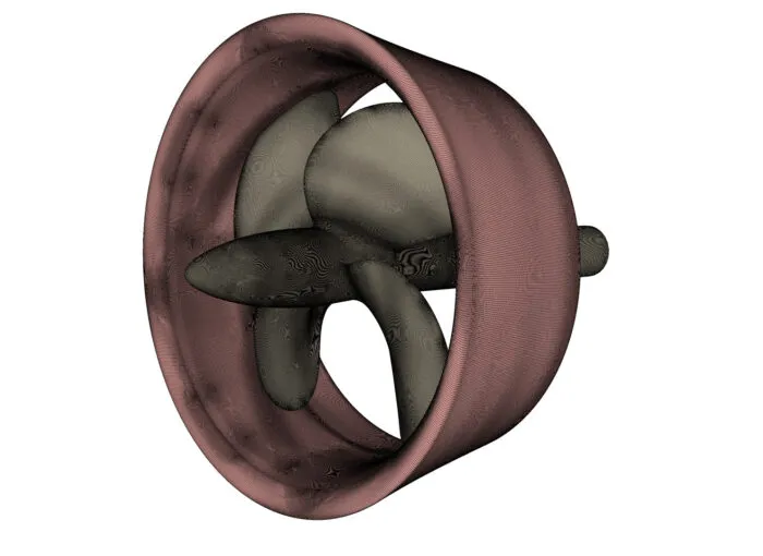
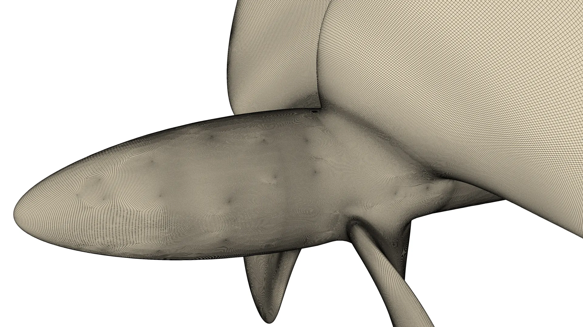
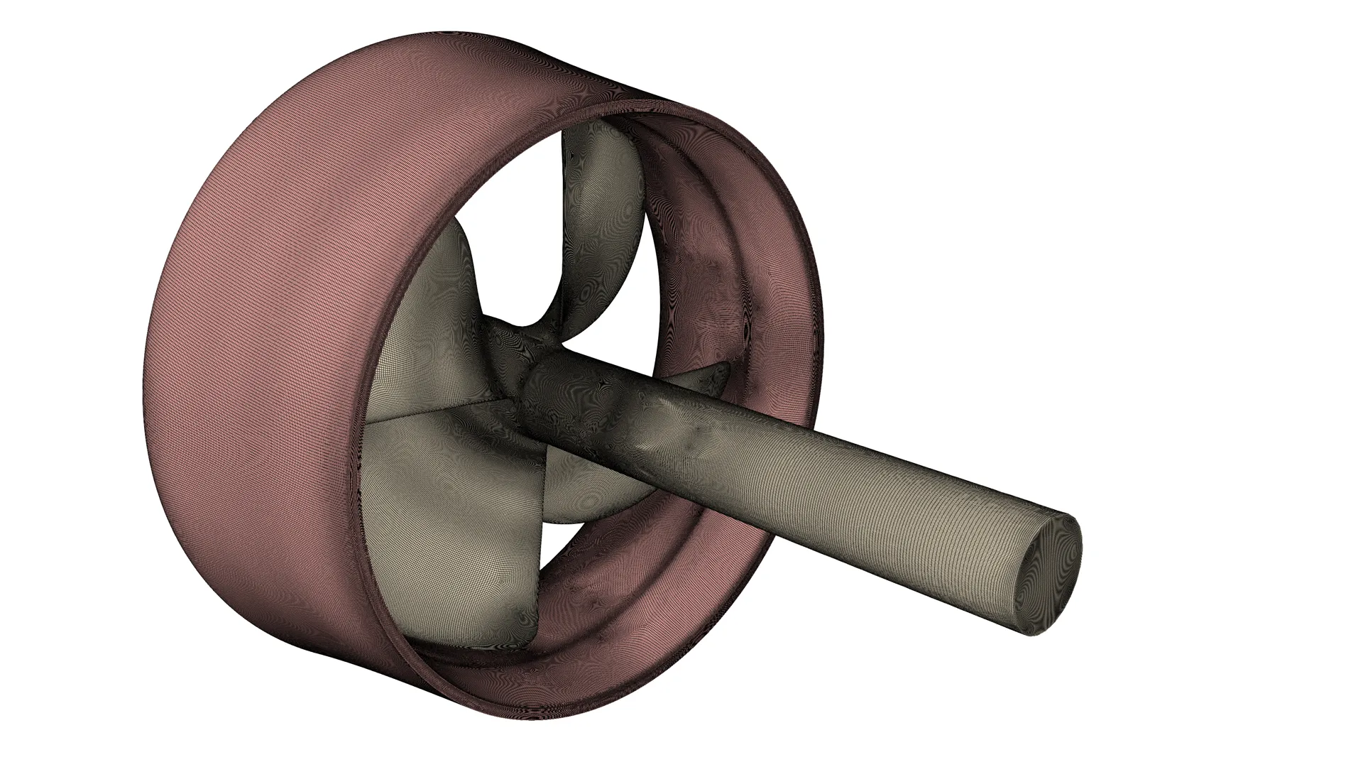
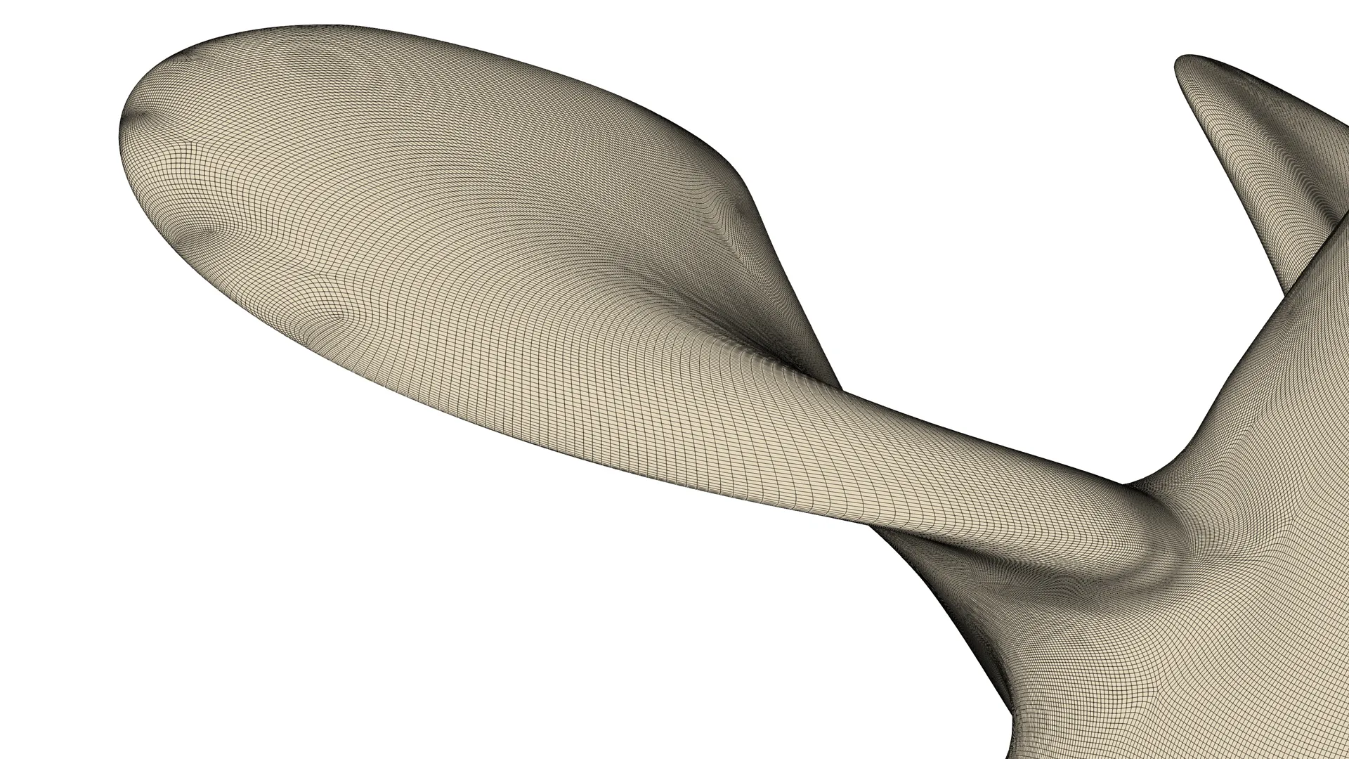
Figure 1: A structured CFD mesh for propeller cavitation analysis — surface resolution on a ducted propeller’s duct and blades.
A CFD engineer’s field guide to mesh design for propeller cavitation — built for simulations that match real life
Here’s a claim that might sting a little: if your propeller mesh isn’t built around the wake, your cavitation results are probably wrong. Not “off by a bit.” Wrong. The vortex is there in real life. Your solver just can’t see it.
Getting the CFD mesh right for propeller cavitation is mostly a geometry problem, not a physics problem — and it’s one most engineers only half-solve. Let’s talk about why that happens, and what the research actually says you can do about it.
Why a Bad CFD mesh Loses Propeller Cavitation
Every propeller sheds two spiral ropes of water: one off each blade tip, one where the blades meet the hub. Inside the core of each rope, pressure drops. Drop it far enough and the water boils — not from heat, but from pressure. That’s cavitation. Tip vortex cavitation is usually the first kind you’ll see on a well-designed propeller, and it’s a major source of underwater noise, which is part of why the IMO has been paying closer attention to it lately (Ref 10).
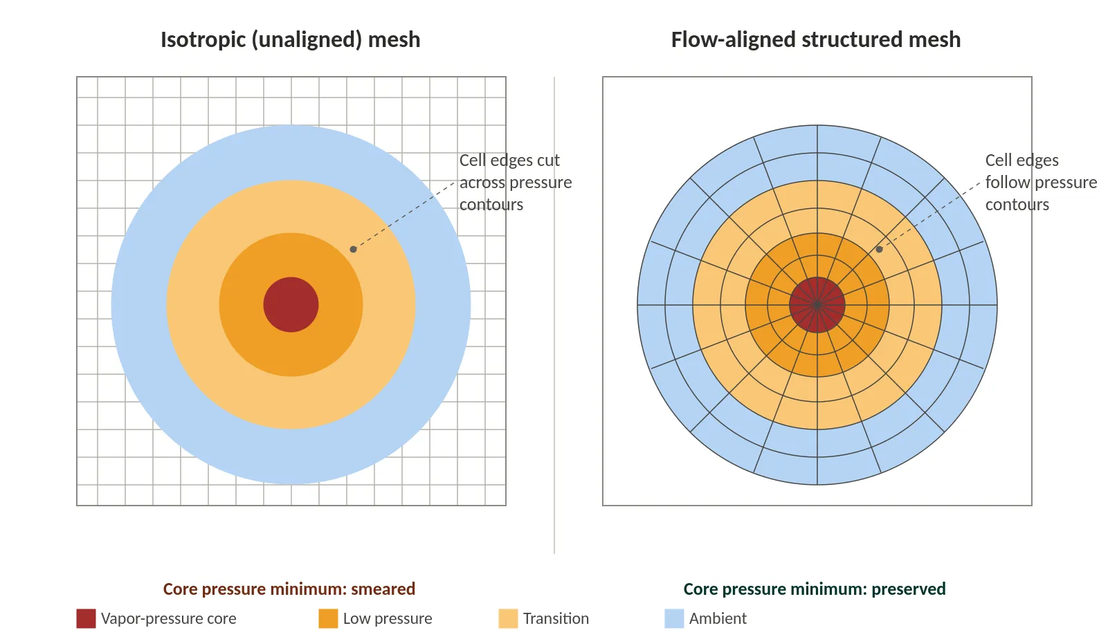
A cavitation model watches pressure in each cell. When it drops below vapor pressure, the model turns liquid into vapor there. So your prediction is only as good as your pressure field — and that’s where most meshes fail. RANS solvers assume turbulence behaves the same in every direction, which smooths out the sharp pressure drop at a vortex core. Picture fog rolling over a canyon: the canyon’s still there, just harder to see. The further the vortex travels through misaligned cells, the worse it gets (Ref 4).
How fine does the mesh need to be? Menter’s rule of thumb for these “globally unstable” flows works out to about 10–20 cells across the vortex, as cited in Ref 4. That’s achievable if your mesh lines up with the flow. If it doesn’t, you pay for it in absolute terms — one detailed study needed a cell size of DProp/2880 right at the vortex core just to converge (Ref 5). Stretch that across a few propeller diameters of wake, and a routine design run becomes a multi-day supercomputer job.
Point Your Cells the Way the Water is Going
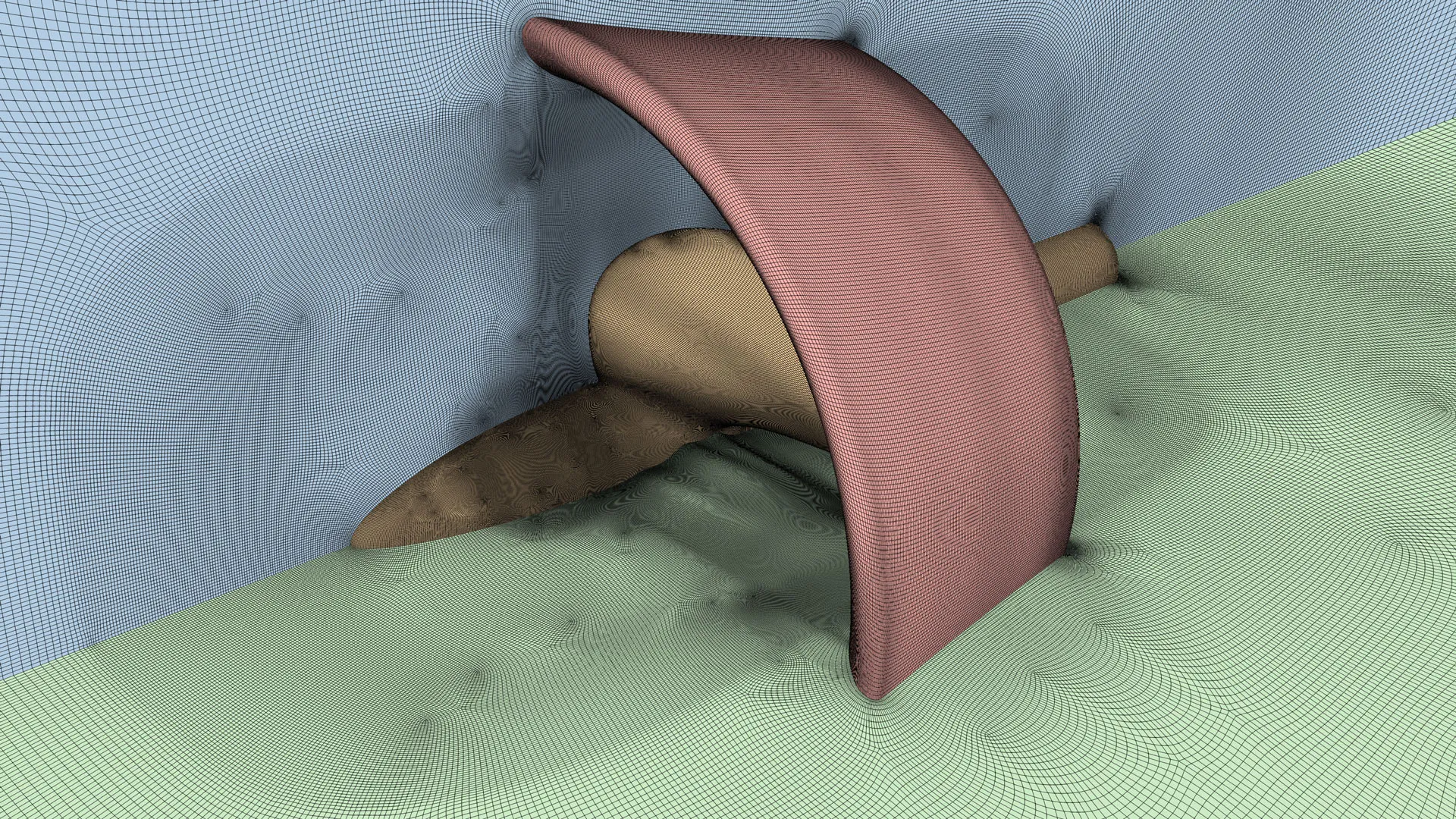
A structured multi-block mesh with hexahedral cells aligned to the helical wake changes the equation. You still need fine resolution across the core, but you can stretch cells along the direction of travel, where the flow is smooth anyway. That’s the core idea behind good CFD mesh design for propeller cavitation: put resolution where the physics needs it, not everywhere at once. Exactly how much you save depends on your geometry and solver, so treat this as a direction to test, not a fixed number — run your own grid convergence study before you lock anything in.
Adaptive mesh refinement (AMR) is a solid alternative. Ref 4 ran an AMR update seeded from a converged solution and found it barely changed the propeller’s overall forces, and solvers like ReFRESCO have dedicated AMR modules built for reliability (Ref 2). The trade-off: every remesh interpolates your solution onto a new grid, which can create small pressure blips right at the update. For forces, that washes out. For acoustic work, chasing pressure fluctuations of a few pascals, it can pollute your signal. A pre-built structured mesh that never changes topology sidesteps this, at the cost of more upfront meshing effort.
A propeller rarely gets simulated alone for long, either. Rudders and ducts interact with the wake behind it, and since the propeller spins while the rudder doesn’t, tracking a vortex across that boundary means handling two reference frames at once. Overset (Chimera) grids solve this by giving each part its own structured mesh and letting them overlap and move independently, so the pressure gradients survive the hand-off much better than they would on one shared unstructured mesh.
The Tip Gap Has More Going On Than You’d Think
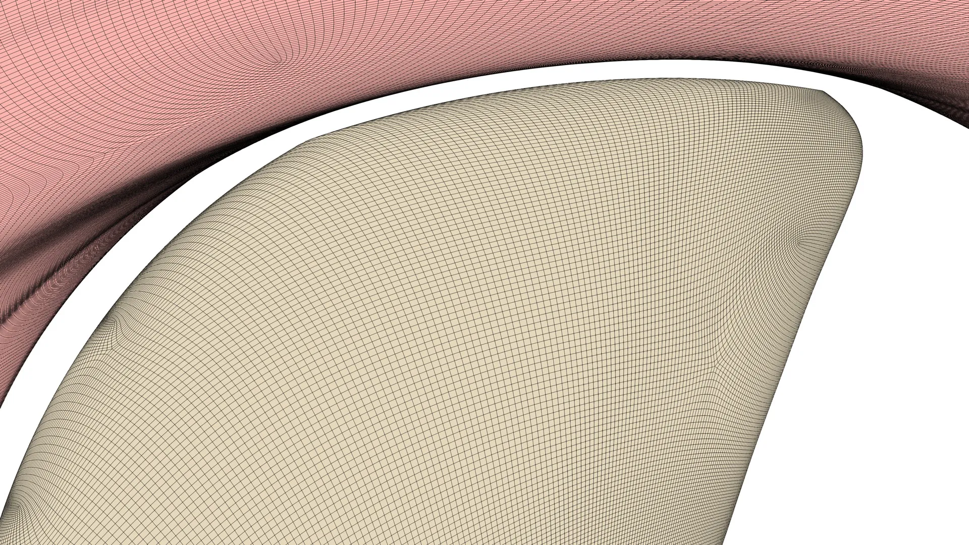
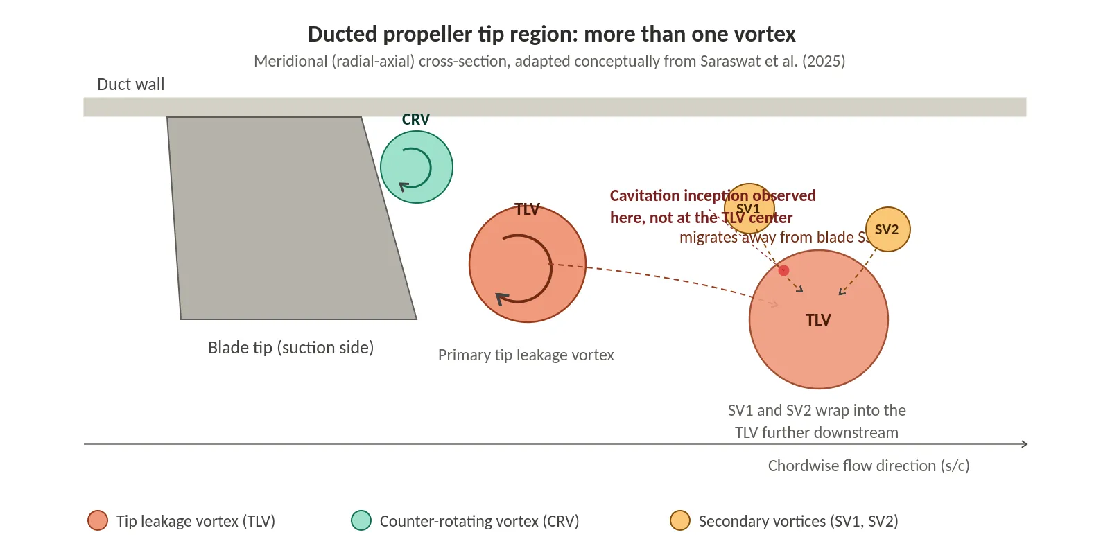
For ducted propellers, the tip-to-duct clearance might be a few millimeters — easy to picture as one single leakage vortex. Recent high-resolution measurements found several vortices working together instead: the main tip leakage vortex (TLV), a counter-rotating vortex (CRV) from duct boundary-layer separation, and secondary vortices that merge into the TLV downstream (Ref 13). Cavitation didn’t even start at the strongest vortex’s core — it started in these smaller structures, where they got stretched by their neighbors. That means a simple O-grid built around one assumed vortex may resolve the wrong thing. Build enough resolution to capture the roll-up and merging of several vortices, not just to fill the gap.
The Hub Vortex: A Rare Case With Real Numbers
The hub vortex, a rope-like cavity where blade-root vortices merge under the hub cone, is a major noise source on its own and can erode a rudder in its path (Ref 10). A 2022 study found something useful: controlled surface roughness on the hub cut hub vortex cavitation volume by up to 50%, for roughly a 0.25% efficiency cost (Ref 10). That’s a good trade for a retrofit — but only if your mesh handles wall physics correctly. The study needed y+ above 30, built on purpose, not left to default settings. Structured meshes make that easy by growing controlled-thickness layers straight off the surface.
One more wrinkle: nearly all this guidance comes from model-scale tests. Full-scale propellers run at much higher Reynolds numbers, and cavitation inception doesn’t scale in a straight line — the scaling exponent keeps dropping as Reynolds number climbs (Ref 5, Ref 12). Don’t reuse model-scale mesh settings at full scale without rechecking them.
Tools Built for Exactly This Job
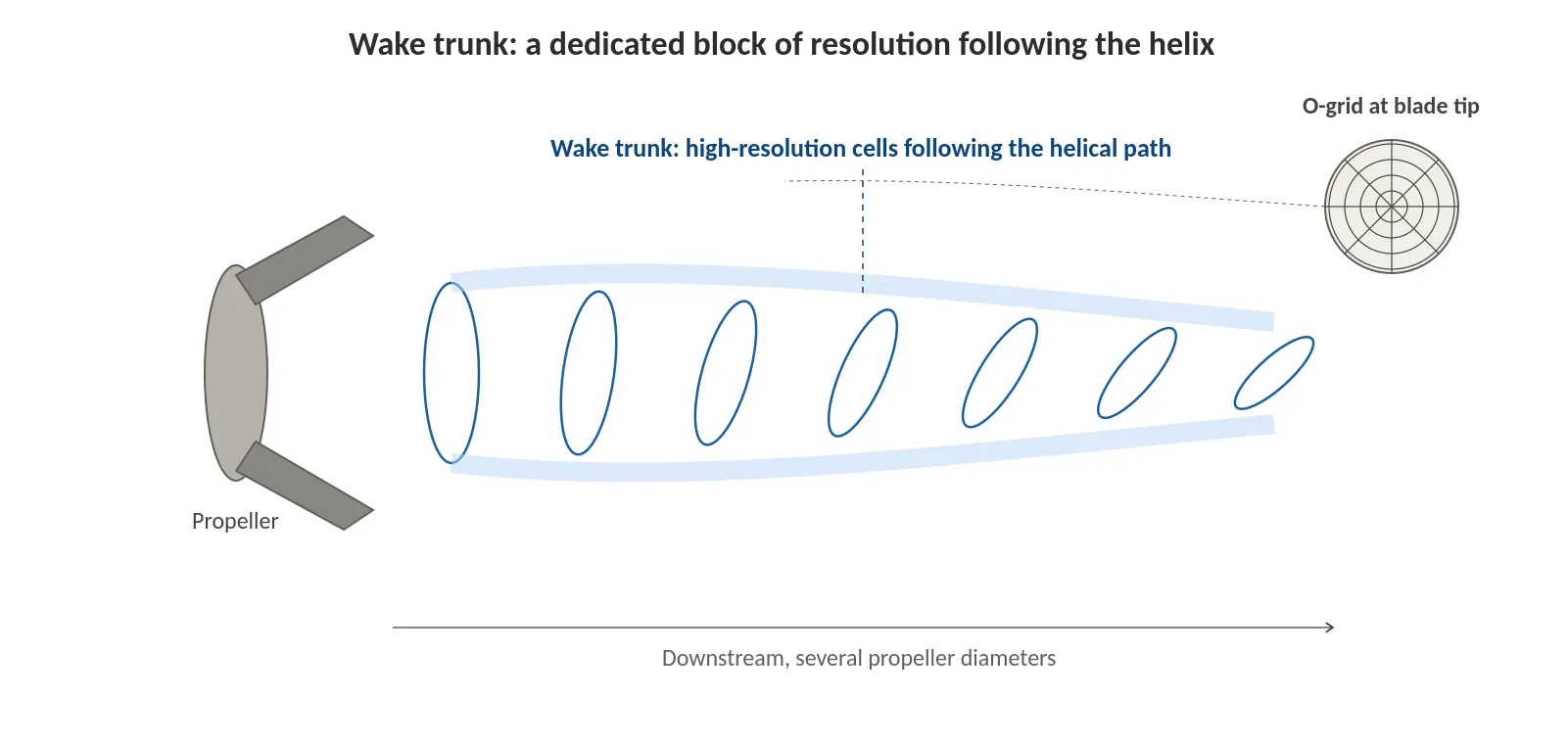
GridPro’s topology-based tools treat the wake as a physical object. A “wake trunk” — a block of flow-aligned, high-resolution cells following the helical path for several diameters downstream — keeps the vortex core resolved without refining the whole domain. Specialized O-grids handle the hand-off from the blade surface into the moving wake block, and keeping size transitions smooth avoids artificial pressure reflections that matter most for acoustic work.
Quick Reference: Mesh Guidance by Region
| Region | What the research shows | What that means for you |
| Tip vortex core | ~10–20 cells across the core for aligned meshes (Ref 4); D/2880 needed if unaligned (Ref 5) | Alignment cuts cell count; misaligned meshes need brute-force size |
| Tip gap | Multiple co-existing vortices, not one gap vortex (Ref 13) | O-grid needs resolution to separate structures, not just fill the gap |
| Hub vortex / wall layer | y+ above 30 needed for correct roughness modeling (Ref 10) | Build near-wall layers on purpose, not by default |
| Full-scale vs. model-scale | Scaling exponent drops with Reynolds number (Ref 5, Ref 12) | Re-check mesh at full-scale Reynolds number |
Questions Engineers Actually Ask
How many cells do I need to catch tip vortex cavitation?
Roughly 10–20 cells across the core for an aligned mesh, as cited in Ref 4; as small as DProp/2880 for an unaligned one (Ref 5). Flow alignment is what gets you the lower number without the size penalty.
Does hub roughness always help?
In the one controlled study available, yes — up to 50% less cavitation volume for about 0.25% efficiency cost (Ref 10). Verify it on your own geometry before assuming it’s universal.
Can I reuse my model-scale mesh settings at full scale?
Not automatically. Cavitation inception scaling depends on Reynolds number (Ref 5, Ref 12), so resolution that worked at model scale needs to be re-checked at full-scale Reynolds numbers, not just copied over.
The Bottom Line
Cavitation happens wherever pressure drops below vapor pressure — that never changes. What changes with a flow-aligned structured mesh is whether your solver can actually see it, without demanding a cell count you don’t have time or hardware for. Treat every number in this article, including ours, as a starting point. Run your own grid convergence study before you trust it. That’s really the whole story of CFD mesh design for propeller cavitation: give the solver a fair shot at seeing what’s actually there.
Want to talk through applying flow-aligned structured meshing to your own propeller, duct, or rudder geometry? Get in touch with the GridPro team.
Further Reading
- Multiblock Meshing of Ship Propeller
- Meshing Aspects for Open Water Marine Propeller CFD
- Influence of Mesh in Open Water Propeller Blade CFD
References
1. Adaptive Mesh Refinement for Trailing Vortices Generated by Propellers in Interaction with Slipstream Obstacles. Geese, J., Kimmerl, J., Nadler, M., & Abdel-Maksoud, M. (2023). Journal of Marine Science and Engineering.
2. Adaptive Mesh Refinement in Marin’s Viscous Flow Solver ReFRESCO: Implementation and Application to Steady Flow. Windt, J., & Klaij, C. M. (2011). MARINE 2011.
3. CFD Analysis of Propeller Tip Vortex Cavitation in Ship Wake Fields. Shin, K.-W., & Andersen, P. (2018). Proceedings of CAV2018.
4. CFD Modelling of Hydroacoustic Performance of Marine Propellers: Predicting Propeller Cavitation. Krasilnikov, V. (2019). NuTTS 2019.
5. Development of a Mesh Refinement Process for the Prediction of Propeller Tip Vortex Cavitation. Doherty, R., Alderton, J., & Batten, W. (2019). NuTTS 2019.
6. Effect of Blade Number on Tip Vortex Cavitation of Propeller. Wang, Y., Xiao, Y., Fang, B., Li, W., Duan, C., Zhang, W., & Hu, J. (2025). Journal of Marine Science and Engineering.
7. Effects of Tip Vortex Cavitation on the Hydrodynamic and Hydroacoustic Performance of a Marine Propeller. Xie, B., Shen, Z., Cao, L., & Wan, D. (2026). Ocean Engineering.
8. Large-Eddy Simulation of the Tip Vortex Flow in a Ducted Propulsor. Leasca, T. J. T., Kroll, T. B., & Mahesh, K. (2025). Journal of Fluid Mechanics.
9. Mesh Refinement Investigation to Simulate Tip Vortex Cavitation under Non-Cavitating Conditions. Huynh, L. H. T., Tran, D. T., & Truong, D. D. (2024). Dynamics.
10. Mitigation of Hub Vortex Cavitation with Application of Roughness. Sezen, S., & Atlar, M. (2022). Journal of Marine Science and Engineering.
11. Propeller Tip Vortex Cavitation Mitigation Using Roughness. Asnaghi, A., Svennberg, U., Gustafsson, R., & Bensow, R. E. (2019). MARINE 2019.
12. Scaling of Tip Vortex Cavitation Inception for a Marine Open Propeller. Hsiao, C.-T., & Chahine, G. L. (2008). 27th Symposium on Naval Hydrodynamics.
13. Tip Leakage Flow Structure and Cavitation Inception in a Ducted Marine Propeller. Saraswat, A., Panigrahi, C., Singh, K., & Katz, J. (2025). Flow.
14. Tip Vortex Cavitation Inception Estimation at an Industrial Level. Svennberg, U., Ahl, D., & Asnaghi, A. (2019). smp’19.
15. Vortex Structures in the Wake of a Marine Propeller Operating Close to a Free Surface. Di Mascio, A., Dubbioso, G., & Muscari, R. (2022). Journal of Fluid Mechanics.