
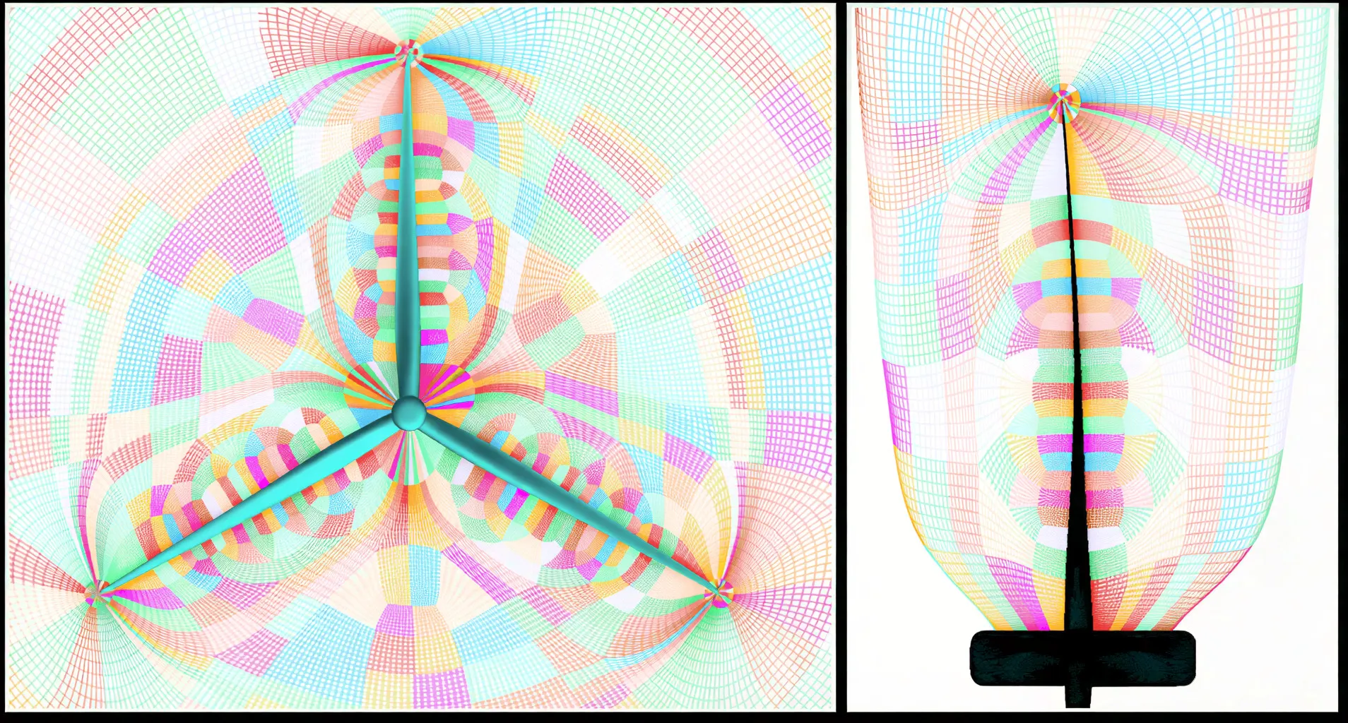
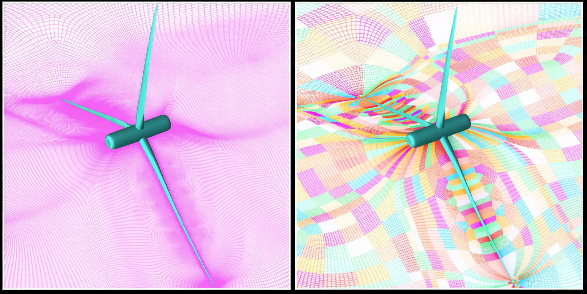
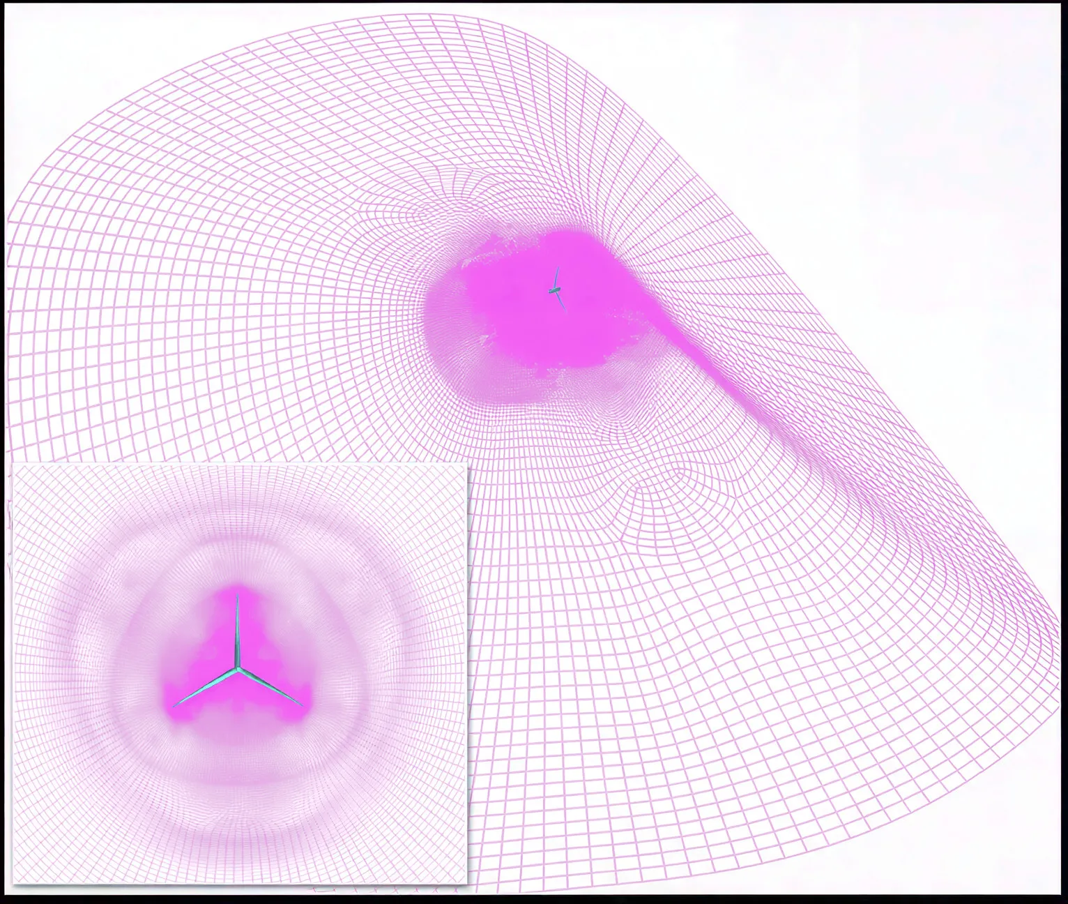
Figure 1: LES structured mesh for capturing tip vortices.
2050 words / 10 min read
Tip vortices are small, powerful tornadoes of air that form at the blade tips. If your mesh erases them, your near-wake loads, noise predictions, and downstream flow are wrong. This article shows practical mesh rules, topology recipes, and a short GridPro workflow so you can keep those vortices alive in LES.
Introduction
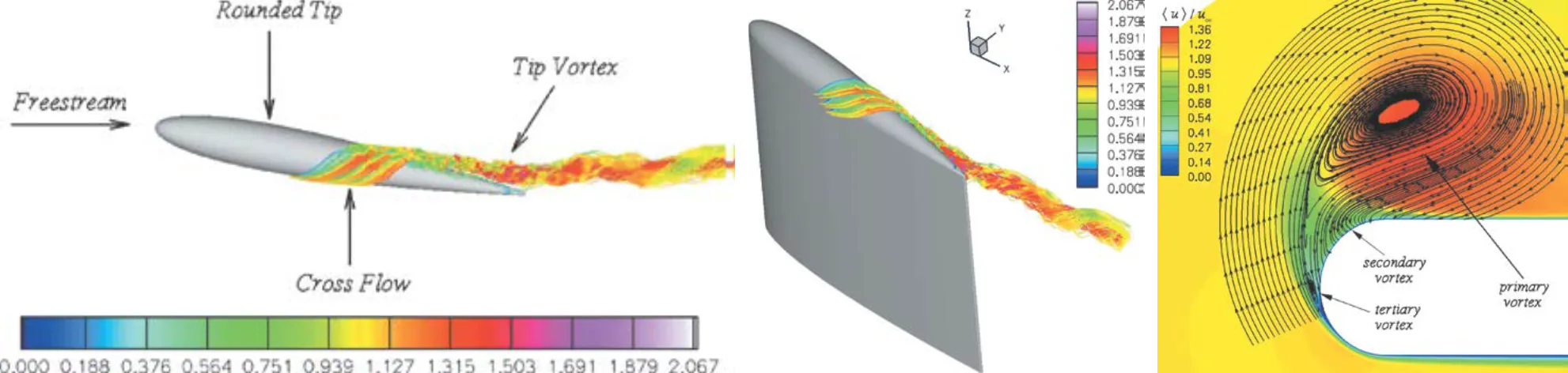
The atmosphere and a spinning wind turbine make a turbulent partnership. At each blade tip, air curls into a tight vortex — a compact spiral of energy that dominates the near‑wake and influences noise, loading, and downstream flow. Capturing this vortex accurately is one of the hardest parts of wind‑turbine CFD.
Large‑eddy simulation (LES) can reveal the unsteady rhythm of these vortices, but it demands a carefully crafted mesh. When cell sizes are uneven or the topology doesn’t follow the physics, numerical diffusion slowly erodes the vortex core — as if the grid itself were dissolving the swirl. The result: a blurred wake and unreliable predictions.
This article provides clear, meshing insights, practical meshing rules, and a three‑step GridPro recipe to build structured multi‑block meshes that keep the vortex intact.
Why Tip Vortices Deserve Our Attention
At first glance, tip vortices seem like a byproduct of lift — a natural twist of air peeling away from the blade edge. But their influence reaches far beyond the tip. These swirling cores of vorticity dictate how the near‑wake forms, how quickly it mixes, and how much energy remains in the flow downstream.
Accurate prediction of tip vortices matters because they:
- Shape aerodynamic loads: The pressure field they induce affects bending moments and structural fatigue.
- Generate noise: The strength and coherence of the vortex core correlate directly with broadband and tonal noise components.
- Control wake behaviour: As vortices interact, they merge, wander, or decay, influencing downstream turbine performance and farm efficiency.
When these vortices are lost to numerical diffusion or under‑resolved meshes, the simulation paints a false picture — smoother, quieter, and more efficient than reality. Capturing them faithfully is therefore essential for credible CFD and reliable design insight.
LES Basics for Tip‑Vortex Problems
LES bridges the gap between time‑averaged RANS and the fully resolved DNS. It resolves the large, energy‑containing eddies while modeling only the smallest turbulent scales. This balance makes LES especially powerful for studying the unsteady, 3D nature of tip vortices.
Unlike RANS, which smooths out turbulence into averages, LES captures the living, breathing dynamics of the vortex — its roll‑up, wandering, and eventual decay. Yet this fidelity comes at a price: the mesh must be fine and well‑structured enough to represent the vortex core. Too‑coarse cells will diffuse the vortex before it even leaves the rotor plane.
For high‑accuracy wind turbine analysis, blade‑resolved LES delivers the richest detail, capturing boundary layer detachment, tip roll‑up, and near‑wake turbulence. However, it demands considerable computational resources. When a broader, more economical view is needed, actuator‑models offer a useful compromise, but they miss the fine vortex-core details present in blade resolved LES.
In short, LES transforms CFD from a static average into a dynamic story — showing how each tip vortex forms, interacts, and fades across the wake.
Mesh Objectives and Quantitative Grid Rules
Designing a mesh for tip-vortex resolution is as much regarding accuracy as it is about strategy. The grid must follow the physics — resolving the vortex core, preserving gradients, and controlling numerical diffusion. Here are key guidelines distilled from rotorcraft and wind-turbine studies:
- Cells across the vortex core: Aim for 5–7 cells across the diameter of the vortex core. This resolution retains the strength and structure of the vortex as it moves downstream. Anything coarser and the flow will appear smoother than reality — the vortex will dissipate numerically long before physics says it should.
- Near-wall resolution: Capture the blade’s boundary layer and the roll-up at the tip accurately. Maintain appropriate y+ values for your turbulence model (often near 1 for wall-resolved LES). A well-resolved viscous region ensures that the tip shear layer transitions correctly into the vortex.
- Smooth stretching: Limit grid growth ratios to around 1.2–1.3. Gradual stretching minimizes interpolation errors and prevents energy loss across block interfaces.
- Aspect ratios: Keep cell aspect ratios moderate and consistent near the tip to avoid numerical anisotropy. The flow near the vortex is highly three-dimensional and sensitive to abrupt grid changes.
- Domain size and grading: Extend the mesh downstream for at least 2–3 rotor diameters when studying the near-wake. Begin with a refined zone around the tip and core, then expand smoothly outward to reduce computational load without compromising fidelity.
These principles provide a foundation for accuracy and stability in LES. Adjust upward for higher‑order schemes or acoustic applications where you need more than minimum fidelity. Once the mesh satisfies these geometric and numerical conditions, the solver can focus on capturing physics — not compensating for poor grid design.
Why Structured Multi‑Block Meshes Help
When the goal is to capture delicate flow structures like tip vortices, mesh organization becomes as important as mesh density. Structured multi‑block grids provide a level of precision and predictability that unstructured approaches have difficulty to achieve.
In a structured multi‑block mesh, every hexahedral block is deliberately placed and smoothly connected to its neighbors. This continuity keeps grid lines aligned with the surface and flow direction, minimizing interpolation errors and numerical diffusion — both of which can diminish vortex strength. Because of this inherent order, the vortex core remains sharply defined as it travels through the wake.
Why Multi‑Block Structured Meshes Stand Out:
- Flow alignment: Cells can be oriented along local streamlines, preserving gradients and lowering dissipation across the vortex path.
- Targeted refinement: Specific zones, such as the blade tip and wake trunk, can be refined locally without increasing the global cell count.
- Smooth block transitions: The gradual size variation between blocks prevents reflections and ensures a consistent numerical environment for LES solvers.
- Solver performance: Structured connectivity enables efficient domain decomposition and quicker convergence on parallel systems.
In short, a well‑crafted multi‑block mesh doesn’t just model the geometry — it reflects the flow physics. For engineers studying tip vortices, that alignment between design and dynamics can make the difference between a simulation that blurs the physics and one that brings it vividly to life.
Practical Meshing Strategies (Step‑by‑Step)
Building an LES-ready mesh for tip-vortex studies is both an art and a science. The objective is to capture every critical detail near the blade tip without inflating computational cost. The following structured framework balances accuracy and efficiency:
- Define a clear topology: Begin with an O-grid wrapping around the blade tip. This topology aligns grid lines tangentially with the surface, guaranteeing smooth vortex roll-up and limiting numerical diffusion.
- Construct a wake trunk block: Extend a cylindrical or helical block downstream from the tip. Maintain fine resolution for the first 1–3 rotor diameters, where the vortex remains coherent, then expand the mesh gradually to reduce cost.
- Resolve boundary layers accurately: Incorporate prism or near-wall layers along the blade surface to capture the boundary-layer growth and shear roll-up. These layers should merge seamlessly into the hexahedral core.
- Refine locally where it matters: Concentrate refinement near the tip and along the expected vortex path. Ensure 5–7 cells across the vortex core to maintain its strength and structure. Apply radial refinement in the O-grid and axial refinement along the wake trunk.
- Maintain seamless transitions between blocks: Avoid abrupt jumps in grid size or direction. Gradual grading between blocks enhances solver stability and maintains smooth vortex transport.
- Use adaptive refinement for long wakes: For extended wake simulations, employ adaptive or feature-based grid refinement strategies that detect regions of high vorticity or velocity gradient.
- Match with suitable numerical schemes: Even the best-designed mesh can fail if paired with a diffusive solver. Combine your structured grid with high-order spatial schemes such as WENO or compact finite differences to preserve the vortex core.
This workflow ensures that the mesh serves the physics — providing resolution where it’s essential and efficiency where it’s permissible — creating a dependable foundation for LES of wind-turbine tip vortices.
Numerical Methods, Sub-grid-scale Interaction and Verification
The fidelity of an LES depends not just on the mesh but on how the numerical scheme and subgrid-scale (SGS) model interact with it. A well-crafted grid can only preserve vortices if the solver accurately transports their structure and strength.
Coupling between Mesh and Numerical Scheme: A structured mesh minimizes geometric errors, but its true potential is realized only with the right numerical method. High-order schemes such as WENO, compact finite differences, or spectral-like formulations are ideal for vortex preservation, as they introduce minimal numerical diffusion. Conversely, low-order upwind schemes may smooth the flow excessively, erasing vortex detail even on refined meshes.
Role of SGS Modeling: The SGS model bridges the gap between resolved and unresolved turbulence scales. Models like Smagorinsky, dynamic Smagorinsky, or WALE need thoughtful calibration for rotating flows — too much eddy viscosity dampens the vortex core, while too little causes instability. The key is balance: the mesh and SGS model must complement, not compete with, each other.
Verification and Diagnostics: Before launching full-scale simulations, validate the setup via systematic checks:
- Grid convergence: Examine vortex strength, trajectory, and core radius across mesh refinements.
- Circulation monitoring: Track vorticity and circulation along the wake to detect artificial decay.
- Cross-validation: Compare results using experimental data or trusted references such as the NREL data set.
- Sensitivity analysis: Test the influence of SGS coefficients and stretching ratios to confirm physical consistency.
Ultimately, accurate LES is a three-way collaboration between mesh design, numerical fidelity, and SGS modeling. When these elements are harmonized, the simulation reproduces vortex evolution that is both numerically stable and physically true.
GridPro Recipe: A 3‑Step Workflow for Tip‑Vortex LES
Creating a high-quality structured mesh for tip-vortex LES becomes straightforward with GridPro, which simplifies topology design, refinement, and quality control. The following three-step workflow helps engineers align grid precision with flow physics while maintaining efficiency.
Step 1 — Build the Block Template: Begin with a multi-block topology for one blade passage. Use an O-grid around the blade tip to capture the vortex roll-up, attach a hexahedral wake trunk downstream, and connect it smoothly to the far-field. GridPro’s topology templates ensure clean block connectivity and consistent indexing, avoiding common meshing errors.
Step 2 — Apply Refinement and Boundary Layers: Next, refine locally where the flow demands detail.
- Add prism layers near the blade surface for accurate boundary-layer capture.
- In the O-grid, ensure 5–7 cells across the vortex core to preserve its strength.
- In the wake trunk, maintain axial growth ratios ≤ 1.2 for uniform resolution.
GridPro’s interactive controls make it easy to visualize spacing gradients and maintain smooth transitions between regions.
Step 3 — Quality Checks and Export: Run GridPro’s quality metrics for skewness, orthogonality, and smoothness. Adjust grids where necessary, then export directly to solvers such as OpenFOAM, or commercial CFD codes. Perform a short vortex-conservation test to confirm stable vortex strength before committing to full LES runs.
By following this three-step workflow, engineers can create LES-ready structured meshes that precisely capture the physics of tip vortices—preserving coherence, reducing diffusion, and ensuring solver efficiency from the very first iteration.
Conclusion — Seeing the Vortex Clearly
Capturing tip vortices through LES is not just a numerical exercise—it’s an insight into how nature sculpts motion out of energy. Each vortex that leaves a blade tip carries the signature of aerodynamic design, surface finish, and flow physics. The mesh simply decides whether that story is preserved or erased.
The essence of good LES meshing lies in intent. When the grid is shaped with an understanding of how vortices form, stretch, and decay, it transforms into more than a numerical scaffold—it becomes part of the physics. Structured multiblock meshes, refined judiciously and verified systematically, offer that accuracy and reliability.
Ultimately, successful LES of tip vortices is an act of balance. The engineer needs to balance resolution against cost, refinement against reach, and fidelity against practicality. Tools like GridPro help bridge that gap—translating aerodynamic intuition into a grid that respects the laws of motion.
A well-designed mesh doesn’t just compute the flow; it reveals it. And in the swirling trail of a single vortex lies the silent proof of a simulation done right.
Interested in Using GridPro for Your Wind Turbine Meshing Projects?
GridPro’s advanced multi-block structured meshing tools deliver the precision, efficiency, and scalability needed for aerodynamic simulations of turbine blades and rotors.
Click Here to Learn More or Request a Demo.
Further Reading
- How CFD Meshes Are Built for Modern Wind Turbine Blades: Why Structure Still Wins
- The Best Way to Mesh Vortex Generators (VGs) for Accurate Wind Turbine CFD
- Automated Hexahedral Meshing with GridPro: Structured Meshes for Parametric Geometry Variants
- The Art and Science of Meshing Turbine Blades
References
- Porté‑Agel et al. — review of wind‑turbine flows: Wind‑turbine and wind‑farm flows: a review
- NREL highly resolved LES report: NREL highly resolved LES of a wind turbine
- ExaWind blade‑resolved campaign: ExaWind blade‑resolved demonstration
- NASA rotor tip vortex profiling: NASA rotor tip vortex profiling
- Stanford adaptive mesh refinement thesis: Stanford AMR thesis
- MDPI WENO study on blade tip vortices: Enhancing the resolution of blade tip vortices in hover (MDPI)
- Recent tip vortex instability / yawed turbine study (JFM abstract): Evolution and instability of tip vortices behind a yawed wind turbine (JFM)
- “Large-Eddy Simulation of a Wing Tip Vortex on Overset Grids“, Ali Uzun et al, AIAA JOURNAL Vol. 44, No. 6, June 2006.