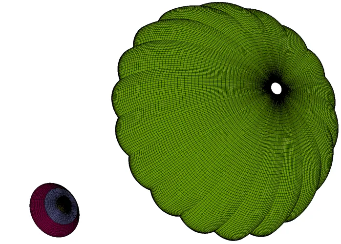
Figure 1: Structured multi-block grid for reentry capsule with supersonic parachutes.
1725 words / 9 minutes read
Introduction
With a surge in interest to go beyond earth’s orbit, space exploration has entered a new arena with many exciting missions planned in the coming years to explore the neighboring planets and other celestial bodies. Right from the days of Vikings, Pioneer Venus, Galileo missions in the last century to recent one’s Mars Pathfinder, Mars Exploration Rovers, Beagle, and Huygens, aerodynamic decelerators have played a key role in the Entry, Descent, and Landing (EDL) of planetary exploring robotic vehicles.
After entering a planet’s orbit, the safe delivery of the scientific instruments is executed in 3 phases. In the first phase of the EDL sequence called Entry, rigid aeroshells are used to dampen the vehicle speed from hypersonic Mach number to supersonic Mach number. Apart from slowing down the vehicle, it physically protects the lander from heat and decelerating pulses. However, they are unfit to safely place the lander on the planet’s surface as they do not have sufficient drag to slow down the vehicle even further. At this point, aerodynamic decelerators are deployed to reduce the vehicle speed from supersonic to subsonic Mach numbers and thereby complete the Descent and Landing phases of the EDL sequence.
Video 1: Animation video showing the Mars Science Laboratories, Entry Descent, and Landing (EDL) sequence. Video courtesy – NASA Jet Propulsion Laboratory.
So, What are these Aerodynamic Decelerators?
Aerodynamic decelerators by definition are textile devices designed to be deployed at vehicle velocities below Mach 5, i.e, right after the end of the Entry phase. Parachutes and inflatable aerodynamic decelerators also called ballutes, come under this category of decelerating devices.
Parachutes are critical devices in all EDL systems as they provide mass and volume efficient sources for aerodynamic drag. Apart from braking the vehicle speed, aerodynamic decelerators fulfill other critical objectives like providing specific descent rate – this aids in gathering scientific data of the planet’s atmosphere, operating as a drogue by providing stability to the aeroshell or to meet instrumentation requirements, facilitate in deploying further aerodynamic decelerators, provide the required difference in ballistic coefficients during the heat-shield and descent-vehicle separation events and finally provide height and timeline to facilitate the smooth completion of the EDL sequence.

The choice of a particular aerodynamic decelerator depends on the flight regime in which it is intended to be deployed. For low supersonic velocities up to Mach 2, a conical ribbon parachute is the best option. But in conditions of low dynamic pressure (as present in Mars atmosphere) disk-gap-band parachutes (DGB) are ideally suited. For velocities up to Mach 3, hemisflo parachutes are preferred, while above Mach 3, hyperflo parachutes are more suitable. Lastly above Mach 4, ballutes are the most preferred ones.
In the following sections, an attempt to understand the flow physics around Disk-Gap-Band (DGB) parachutes has been made.
Disk-Gap-Band Parachutes
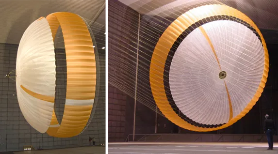
Originally developed during the Viking expedition to Mars during the 1970s, DGB parachutes are the defacto aerodynamic decelerators for all of the US Mars missions to date. Manufactured using materials like Dacron, Kevlar, or Nylon, they are specifically designed to maximize drag and stability at supersonic Mach numbers in environments with low dynamic pressure. Video 2 shows amazing footage of the dynamic unfurling of the DGB parachute in wind tunnel conditions.
Video 2: DCB parachute opening in wind tunnel conditions. Video credit: NASA Langley.
DGB parachutes are best suited for decelerating vehicles with speeds below Mach Number 2. At Mach numbers above 1.5, they experience stability problems which increase in violence with an increase in Mach number. Further, it is observed that the drag coefficient reaches peak values at Mach number between 1.8 and 2.0 and drops off with the increase in Mach number. A closer look at the flow physics reveals the reasons behind this fall in the performance of DGB parachutes.
Understanding the Flow Physics
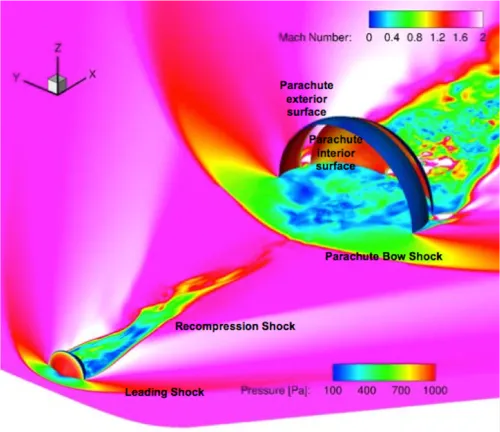
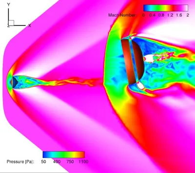
Flow around DGB parachutes are quite complex and are rich in physics. When we look at the flow past a DGB parachute, we can observe two shocks developing, one ahead of the capsule and the other, ahead of the canopy. A narrow turbulent wake develops downstream of the capsule, while a more irregular turbulent wake gets set up behind the canopy. The detached flow downstream of the capsule and the canopy is mended by two recompression shocks, which straighten out the oblique flow direction just behind these bodies and align them with the free stream direction.
Researchers attribute this unsteady phenomenon to aero-elastic effects of the suspension lines, fabric porosity, and entry-vehicle wake interaction at high Mach numbers. Studies have shown that an increase in suspension line length increases the Cd value while an increase in fabric porosity reduces the drag coefficient.
The oscillatory breathing phenomenon can be better understood by conducting an unsteady fluid-structure interaction simulation. Video 3 shows simulation results chronicling the series of events that unfolds leading to the area oscillation. The illustration starts from 0.2 seconds after the complete opening of the parachute for the first time.
Stage 1, t = 0.205 s: A strong curved shock gets established ahead of the capsule and canopy. A high-pressure area builds in the canopy.
Stage 2, t = 0.245 s: Canopy shock transforms from a curved shape to conical. Reverse flow from the high-pressure area in the canopy interior towards the capsule base also begins.
Stage 3, t = 0.285 s: Increase in reverse flow volume observed.
Stage 4, t = 0.325 s: Reverse flow grows further and reaches the capsule base. Capsule bow shock gets modified and the wake recompression shock gets disrupted. Further, the pressure in the canopy drops.
Stage 5, t = 0.365 s: The reverse flow becomes highly unstable. Capsule base flow is completely disrupted and the region turns into a high-pressure zone. In addition, the entire parachute gets engulfed in low energy, low pressure, subsonic flow.
Stage 6, t = 0.405 s: Low pressure around parachute triggers canopy collapse. The flow ahead of the canopy is in a confused state and is subsonic.
Stage 8, t = 0.485 s: Flow around the capsule gets reestablished completely. Pressure increases inside the canopy and the canopy inflates.
Stage 9, t = 0.525 s: Development of clear bow shock ahead of the capsule and canopy. A high-pressure region in the canopy sets in.
Stage 10, t = 0.565 s: Once again the canopy shock becomes conical. Reverse flow from the high-pressure area inside the canopy towards the capsule base begins.
Stage 11, t = 0.595 s: Canopy conical shock moves towards the capsule, reverse flow advances towards the capsule base.
From here on the cycle repeats.

Interestingly, a change in fluid medium from air to carbon dioxide has less impact on parachute performance. CO2, the most prominent gas in the Mars atmosphere has a specific heat ratio of 1.3 while that of air is 1.4. Gamma, the specific heat ratio is known to affect the shock standoff distance and conditions across the shock. However, it doesn’t drastically alter the parachute performance as it was observed that the drag varies by only 2 percent. What this implies is that a high-altitude Earth test is a good proxy for an actual Mars flight.

Parting Thoughts
The supersonic deployment of parachutes is not the same as subsonic low altitude deployment. Structural loads experienced by the parachute in supersonic flows are far greater than those seen at equivalent dynamic pressures in subsonic flows. This has implications for the parachute design. The change in load results in a change in ribbon flutter and canopy shape during flight. This calls for larger design margins and a carefully crafted design, particularly in the skirt region.
Executing the EDL sequences is a nerve-wracking moment for the control team over-looking the operation. With little room for error, the cost of failing to deliver the payload can run into millions of dollars, not to mention the years of human efforts. With so much at stake, supersonic parachutes have proven multiple times in the past to make the odds of delivering the payload successfully on another planet very high. We might not have understood all aspects of supersonic aerodynamics around parachutes, but still, we can design a successful system that can deliver the payload on an uncharted celestial body safely.
Acknowledgment
The structured multi-block grids used in this article were generated by Bruno C. Sotelo as part of his Master’s degree in the Department of Aerospace Engineering, San Jose State University under the guidance of Dr. Periklis Papadopoulos using GridPro. We sincerely thank them for providing the grid images for this article.
Further Reading
- Know Your Mesh for Reentry Vehicles
- Spiked Blunt Bodies for Hypersonic Flights
- Meshing of Rocket Engine Nozzles for CFD
References
1. “Modeling and Flight Performance of Supersonic Disk-Gap-Band Parachutes in Slender Body Wakes”, Suman Muppidi, et al, AIAA Atmospheric Flight Mechanics Conference, Atlanta, GA, June 27th 2018.
2. “Findings from the Supersonic Qualification Program of the Mars Science Laboratory Parachute System”, Anita Sengupta, Adam Steltzner, Allen Witkowski, Graham Candler.
3. “A computational study of supersonic disk-gap-band parachutes using Large-Eddy Simulation coupled to a structural membrane”, K. Karagiozis, Journal of Fluids and Structures 27 (2011) 175–192.
4. “Modeling, simulation and validation of supersonic parachute inflation dynamics during Mars landing”, Daniel Z. Huang, Philip Averyc, Charbel Farhata, Jason Rabinovitchd, Armen Derkevorkiand, Lee D Peterson.
5. “An Embedded Boundary Approach for Resolving the Contribution of Cable Subsystems to Fully Coupled Fluid-Structure Interaction”, Daniel Z. Huang et al, Institute for Computational and Mathematical Engineering, Stanford University, Stanford.
6. “Supersonic Disk Gap Band Parachute Performance in the Wake of a Viking-Type Aeroshell from Mach 2 to 2.5”, Anita Sengupta et al, AIAA Conference Paper, August 18, 2008.
7. “Supersonic parachute”, Steve Lingard, Vorticity Ltd, 3rd International Planetary Probe Workshop, June 27th – July 1st 2005, Anavyssos, Attiki, Greece.
8. “Aerodynamic Decelerators for Planetary Exploration: Past, Present, and Future”, Juan R. Cruz, J. Stephen Lingard, AIAA Conference paper, 2006-6792.
9. “High-Fidelity Grid Generation Investigations of a Low-Density Supersonic Decelerator“, Bruno C. Sotelo, December 2017, Department of Aerospace Engineering, San José State University.