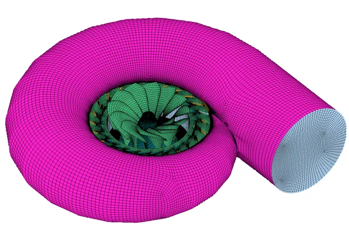
Figure 1: Structured multi-block meshing of Francis turbines.
1600 words / 8 minutes read
This is the first article in a 4-Part series on Hydraulic Turbines:
Part 1 – Understanding the flow through Francis turbine.
Part 2 – Cavitation in turbines.
Part 3 – Influence of Meshes on Hydraulic Turbine CFD.
Part 4 – Grid Convergence Study for Francis Turbine- From a Meshing Software Perspective.
Introduction
Hydraulic turbines have been a power extracting device from water for over two centuries. Historically in the initial phase of their application, water turbines were used widely for industrial power generation. Later, with the advent of electrical grids, they became popular as electrical power generating devices.
There are many types of hydraulic turbines; the most common ones are – Pelton turbines, Francis turbines and Kaplan turbines. Though all three types of turbines are designed to meet the objective of power extraction from water, they differ in their working mechanism and operating conditions.
This article is the first in a series of articles on Hydraulic Turbines, covering various aspects like the difference between Pelton-Francis-Kaplan turbines, the working mechanism, and flow disturbances in Francis turbines.
Pelton-Francis-Kaplan — How are they different?
One of the striking differences is the mechanism by which the rotating force gets generated in the turbine. In Pelton turbines, the pure impulse force of the water jet rotates the impeller. In contrast, in Kaplan turbines, the force is purely reactive. The pressure differential created around the blades generates a lift force that drives the impeller. On the other hand, both impulse and lift force in Francis turbines contribute to power generation.
Another difference is that Pelton turbines are suitable for places with water stored at high altitude, which enables to attain high head and high velocity, while Kaplan turbines are better suited for locations with high water flow rate and low head. Francis turbine comes in between for medium head and medium flow rate applications.
Of the three, Francis turbines can work efficiently for various operating conditions. Hence, it is the most popular among the three and contributes to over 60 percent of global hydropower generation.
In the following section, we will try to understand the Francis turbine in more detail. It will cover aspects like its working mechanism and flow physics, including fascinating physical phenomena like the helical rope vortex.
Video 1: CFD simulation of flow through a Francis turbine.
The Working Mechanism of a Francis Turbine
The turbine consists of an outer spiral casing, followed by a set of fixed blades called stay vanes. Next comes a collection of moving blades called guide vanes, then a bunch of centrally placed blades called runner and lastly, an outgoing duct called a duct draft tube. Figure 2 shows the various parts of a Francis turbine.
The flow enters the Francis turbine through the spiral casing. Decreasing the cross-sectional area of the casing ensures that the flow enters the central part of the turbine with uniform velocity throughout the perimeter.
The flow next passes through two sets of blades before entering the runner, namely – the outer stay vanes and the inner guide vanes. The stay vanes are fixed and help steer the water towards the runner section. They help in reducing the swirl at the inlet flow as well.
The guide vanes sitting in between the stay vanes and the runner have a more critical role to play. They manage the flow rate based on the power demand. But the power demand fluctuates over time. The guide vanes govern the water flow rate and ensure that power production is in sync with demand. In addition, guide vanes control the flow angle directed towards the runner blades. They try to ensure that the inlet flow angle is at the optimal angle of attack to harness maximum water power.

Next, the flow comes in contact with the most crucial part of the Francis turbine – the runner. Water enters the runner radially and leaves axially. Because of this change in the direction across the runner, Francis turbines are called mixed flow turbines.
The runner blades are highly contoured and have thin airfoil cross-sections. So, when water flows over it, one side of the blade experiences low pressure while the opposite side perceives high pressure. This pressure differential creates lift force.
Also, due to the peculiar shape of the blade at the outlet, the incoming water hits the blade outlet and produce impulse force before leaving the runner. Thus, the runner blade generates both lift and impulse forces, which sets it into a rotating motion. So unlike Kaplan turbines, Francis turbines are not pure reaction turbines, as part of the force comes from impulse action also. In other words, both the kinetic and pressure energy of the fluid will be reduced as it leaves the runner.
This low-pressure exit from the runner could lead to severe problems of cavitation. So to avoid it, the outflow is directed towards a carefully designed tube called the draft tube. These tubes with increasing cross-sectional area transform the dynamic head of the fluid to static pressure and thereby reduce the effect of cavitation.
Video 2: A Francis turbine-driven power station in action.
The Onset of Flow Disturbances
In Francis turbines, the runner blades are fixed. They cannot be adjusted to any particular flow regime in the operating range. Hence, they are generally designed for an optimum best efficiency point for a specific discharge. Only for flow regimes around the optimal working conditions, the flow characteristics can be called ideal, with high efficiency and low fluctuations of pressure and output.
However, the power demand is not always constant, and they tend to fluctuate over time. Consequently, turbines are compelled to operate over an extended range of regimes, quite often far away from the best efficiency point. And this comes with a penalty. While running in these off-design operating conditions, the inflow angle to the runner blades may deviate from the ideal flow angle. Also, the flow pattern in the draft tube could change drastically. As a consequence, all these flow modifications will result in swirls, flow separation and backflow.

Figure 3 shows the flow pattern in the draft tube under three different loadings of high load, near BEP and part load, typically seen in Francis turbine.
a. High load
At high loads, water, while entering the draft tube, tends to flow towards the machine axis, creating a swirl against the direction of runner rotation. The static pressure in the swirl center tends to be very low, and when it goes below the vapour pressure, cavitation sets in the vortex core. Usually, this condition is stable with small pressure fluctuations felt in the draft tube. But occasionally, under certain circumstances, the vortex core volume may fluctuate, causing unstable pressure oscillations to propagate through the entire hydraulic plant system.
b. Around Best Efficiency Point
Around best efficiency, the inflow to the runner is at the ideal design blade angle, and the streamlines smoothly follow the geometric contours of the runner blades to a greater extent. Also, inside the draft tube, the flow is more or less smooth and stable with a low swirl intensity.
Video 3: CFD simulation of the rope vortex in the draft tube.
c. Part load
At part-load conditions, i.e. at about 50-80 percent of the best efficiency flow rate, water in the runner tends to flow towards the outer region of the machine. Further, the flow tends to leave the runner with a swirl, rotating in the same direction as the runner. This outflow condition creates a backflow in the center of the draft tube cone and a helical vortex rope.
Experiments have shown that the helical rope vortex has a precession rotation at 0.25-0.35 times the runner rotating speed. Due to the non-axisymmetric movements of the vortex rope, periodic pressure fluctuations of low-frequency set in. In addition, the low pressure inside the vortex core triggers the development of cavitation bubbles.
The frequency of these pressure pulsations is usually a fraction of the rotating frequency of the runner. But suppose this frequency gets close to the natural frequency of the draft tube or penstock. In that case, resonance could occur, triggering large bursts of pressure pulses in the draft tube, causing strong vibrations on the turbine and even on the entire power plant.
Unfortunately, there are no clear solutions to eliminate this problem. Some control methods like air or water injection, runner core extension, mounting of stabilizer fins on the draft tube wall, etc., are often proposed to alleviate pressure fluctuations. But they are not fool-proof and have their inherent limitations.
Experiments have shown that inappropriate air or water injections could further enhance pressure pulsations. At the same time, the idea of extending the runner cone can be prohibitive due to other physical design constraints on turbines. The last approach of installing fins on duct walls is popular, but it is less understood. In a way, this is still an unsolved problem with many ideas floating around. Researchers are still on the lookout for a more tangible solution.
Parting thoughts
Even with such limitations, modern-day Francis turbines developed over many years of research and development can attain hydraulic efficiency in excess of 80 percent and are capable of transforming up to 95 percent of the available potential head into electrical energy.
With this, we come to the end of Part 1 in the series on Hydraulic Turbines. In the following article in the series, titled Cavitation in turbines we try to cover aspects of cavitation in hydraulic turbines, including the cavitation mechanism, different types of cavitation, etc.
Hydraulic Turbine Series
Part 1 – Understanding the flow through Francis turbine.
Part 2 – Cavitation in turbines.
Part 3 – Influence of Meshes on Hydraulic Turbine CFD.
Part 4 – Grid Convergence Study for Francis Turbine- From a Meshing Software Perspective.
References
1. “Detection of cavitation in hydraulic turbines”, Xavier Escaler et al, Mechanical Systems and Signal Processing 20 (2006) 983–1007.
2.“Simulations of Steady Cavitating Flow in a Small Francis Turbine”, Ahmed Laouari, Hindawi Publishing Corporation International Journal of Rotating Machinery Volume 2016, Article ID 4851454.
3. “Analysis of the Cavitating Draft Tube Vortex in a Francis Turbine Using Particle Image Velocimetry Measurements in Two-Phase Flow”, Monica Sanda Iliescu, Journal of Fluids Engineering, February, 2008, Vol. 130.
4. “Vortex ropes in draft tube of a laboratory Kaplan hydroturbine at low load: An experimental and LES scrutiny of RANS and DES computational models”, A. Minakov, Pages 668-685, Journal of Hydraulic Research, Volume 55, 2017 – Issue 5, 24 Apr 2017.
5. “Jet Control of the Draft Tube Vortex Rope in Francis Turbines at Partial Discharge”, Romeo Susan-Resiga et al, 23rd IAHR Symposium – Yokohama, October 2006.
6. “Numerical Study of Cavitation in Francis Turbine of a Small Hydro Power Plant”, P. P. Gohil et al, Journal of Applied Fluid Mechanics, Vol. 9, No. 1, pp. 357-365, 2016.
7. “Dynamic loads in Francis runners and their impact on fatigue life“, U Seidel et al, 27th IAHR Symposium on Hydraulic Machinery and Systems 2014.
8. “Experimental Investigation on the Characteristics of Hydrodynamic Stabilities in Francis Hydroturbine Models“, Wen-Tao-Su et al, Advances in Mechanical Engineering, March 2014.
9.”Investigations of time dependent flow phenomena in a turbineand a pump-turbine of Francis type: rotor-stator interactions and precessing vortexrope”, Ph.D. thesis, Zobeiri, A. (2009) ´Ecole Polytechnique F´ed´erale de Lausanne.
Helpful