
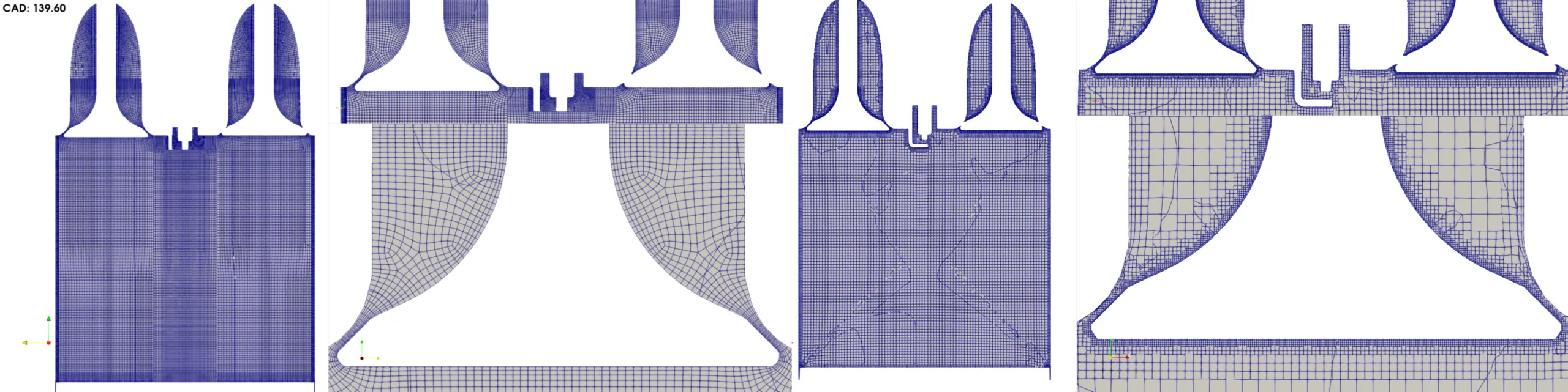
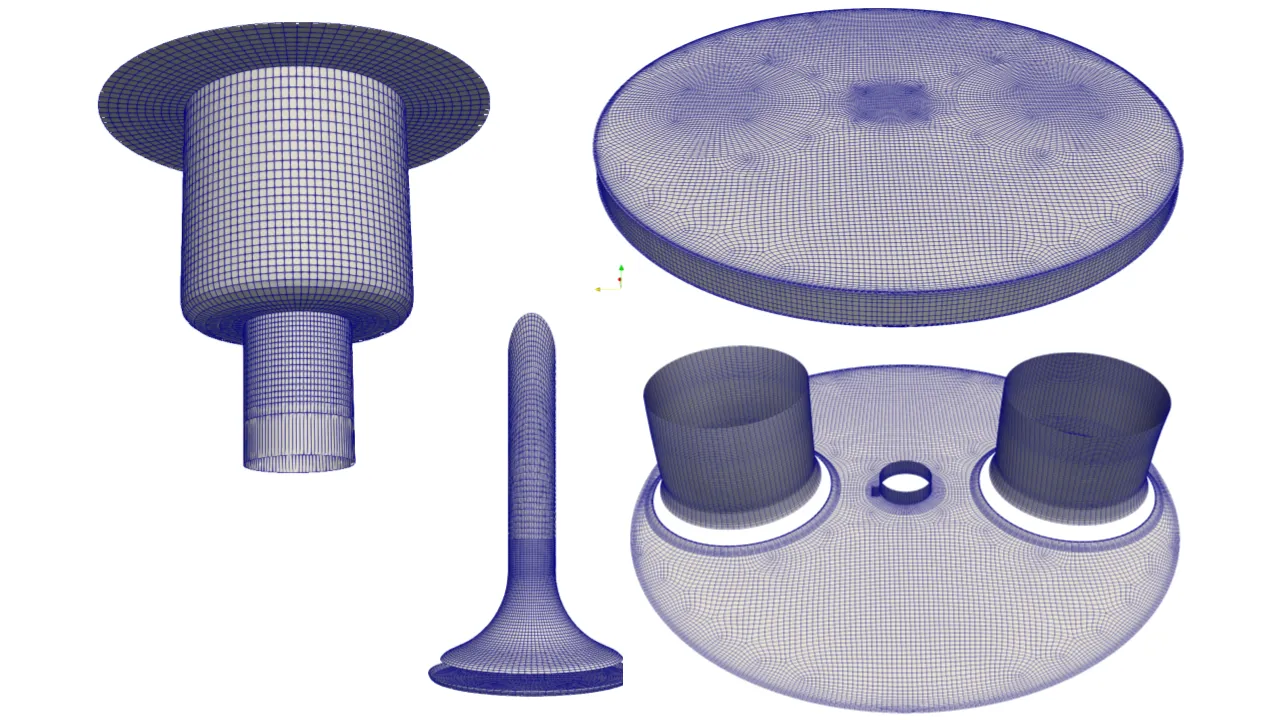
Figure 1: Structured multiblock mesh for high fidelity IC engine CFD.
1553 words/ 8 mins read
High-Fidelity IC Engine CFD is only as accurate as the mesh behind it. Discover why structured multi-block meshing outperforms unstructured Hexahedral dominant grids in capturing valve gaps, moving boundaries, intake vortices, and combustion physics. Backed by the TCC-III benchmark study, this article reveals how mesh topology directly impacts simulation fidelity, stability, and computational efficiency.
Introduction
The internal combustion engine is not going away; it is evolving. As we pivot toward a net-zero future, the industry is moving at lightning speed to adapt current engine architectures for alternative fuels like Hydrogen, Ammonia, and Methanol. But here is the catch: these fuels do not behave like gasoline or diesel. They have different ignition requirements and completely different combustion chemistry. For engineers, this means the era of “good enough” simulation is over. We need modeling that is both incredibly accurate and fast enough to support rapid prototyping.
This brings us to a fundamental fork in the road for every CFD engineer: how do you mesh your engine?. Do you take the automated, unstructured path, or do you invest in a structured, multi-block approach?. A recent landmark study at Aalto University, using the Transparent Combustion Chamber (TCC)-III optical engine, has provided some definitive answers. The research, led by Bishal Shrestha, compared the industry-standard GridPro structured mesher against open-source unstructured tools. The takeaway is clear: if you want to push the boundaries of engine performance, your mesh needs to be structured.
The TCC-III Benchmark: Why It Matters
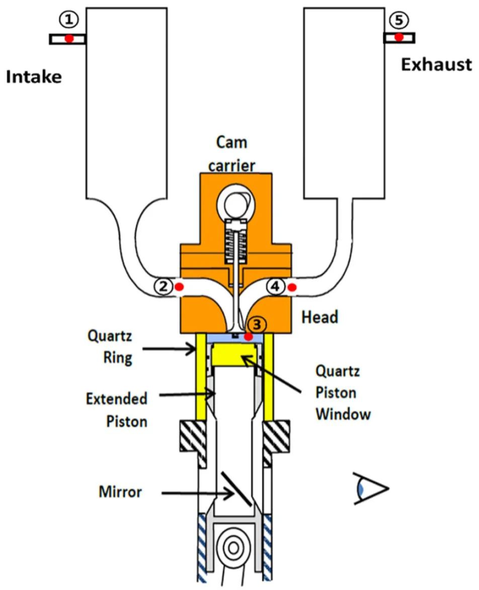
Before diving into the “how,” we have to look at the “what.” The study focused on the TCC-III engine developed at the University of Michigan. This is a simple, 2-valve, 4-stroke engine with a flat cylinder head and a flat piston. On paper, it looks easy. In the world of CFD, however, even a “simple” engine is a complex dance of moving parts and tiny clearances.
The beauty of the TCC-III case is that all the data—the geometry, the boundary conditions, and the experimental Particle Image Velocimetry (PIV) data—is publicly available. This creates a perfect “plug-and-play” benchmarking template for the entire community. “We wanted to create a framework that anyone could download and use to test their methodologies,” says the research team. By using this engine as a baseline, the Aalto study provides a rare, objective look at how different meshing philosophies perform under pressure.
The Philosophy of the Mesh: GridPro vs. SnappyHexMesh
In this study, two heavyweights went head-to-head. On one side, we have GridPro, a commercial tool that generates body-conformed, block-structured meshes. On the other, we have snappyHexMesh, the open-source tool bundled with OpenFOAM that produces unstructured, hexahedral-dominant grids.
The difference in philosophy is night and day. GridPro uses a topology-based workflow. You start by creating a 3-D wire-frame “topology” around your geometry. Using a dynamic boundary-conforming algorithm, this topology morphs into a high-quality multi-block mesh that perfectly aligns with the walls of your engine.
“With GridPro, you aren’t just filling space with boxes; you’re designing the flow path into the grid itself,” notes the researchers. This body-alignment is critical. Unstructured tools like snappyHexMesh often rely on “stair-stepping” to handle curved surfaces, which can lead to inaccuracies near the walls—exactly where the most important physics happen in an engine.
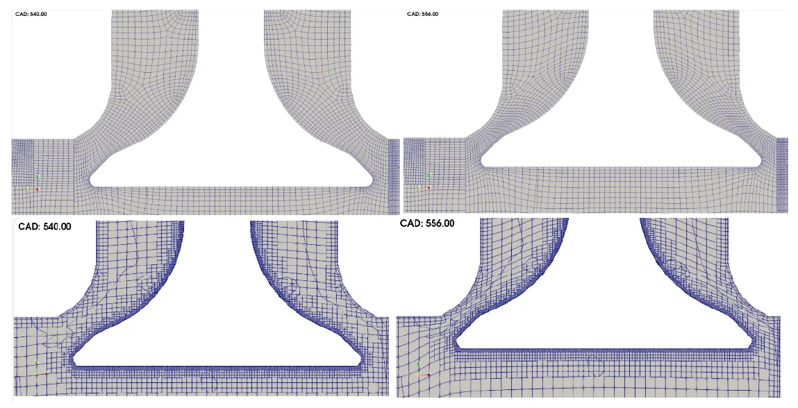
The Gap Problem: Managing Tenths of a Millimeter
One of the most frustrating parts of engine CFD is the valve seat. As a valve closes, the gap between the valve head and the port becomes microscopic. Capturing the flow through this tiny area is essential for getting the intake jet physics right.
The Aalto study highlighted a massive gap in capability here. To capture these small geometries, snappyHexMesh requires massive local refinement. You have to define tiny “refinement zones” with cell sizes as small as 0.125 mm. Even with that level of effort, the open-source tool could only reliably handle a minimum valve gap of 0.45 mm.
GridPro, by contrast, handles these tiny spaces with ease. Because it uses high-aspect-ratio cells that are aligned with the geometry, it successfully simulated valve gaps as small as 0.1 mm. “When you’re trying to model modern combustion, a 0.35 mm difference in your valve gap resolution is the difference between a valid result and a guess,” the study suggests. This ability to resolve tight clearances without blowing up your cell count is a game-changer for high-fidelity work.
Fidelity in Motion: The Resilience of Structured Cells
Engines are not static. The piston and valves are constantly moving, which means your mesh is constantly deforming. If your mesh doesn’t handle this motion gracefully, your simulation is going to crash.
The Aalto study utilized a specialized Wärtsilä in-house mesh mover to handle these dynamics. The mover stretched and compressed the cells as the piston climbed toward Top Dead Center (TDC). Here, the structured resilience of GridPro really shone. Because its cells were body-conformed and aligned with the movement, they deformed uniformly.
Unstructured meshes are far more brittle. They are prone to something called boundary layer collapse, where the cells near the wall become so distorted that they lose all mathematical meaning. To prevent this, engineers have to perform “mesh-to-mesh mapping”—essentially stopping the simulation and starting a new one on a fresh mesh instance every few degrees of crank angle.
The data was striking: because GridPro’s cells resist deformation-driven errors longer, it required significantly fewer mapping instances than the unstructured alternative. In an automated workflow, fewer instances mean fewer potential points of failure and a much smoother road to a high fidelity IC engine CFD simulation.
The Efficiency Payoff: Faster Results, Smaller Footprint
There is a nagging myth in the CFD community that structured meshing is “too slow” because it takes more time to set up. The Aalto research proved that this setup time is a drop in the bucket compared to the actual solve time.
Let’s look at the numbers at TDC—the most computationally intense part of the stroke:
- snappyHexMesh: 2.4 million cells.
- GridPro: 1.4 million cells.
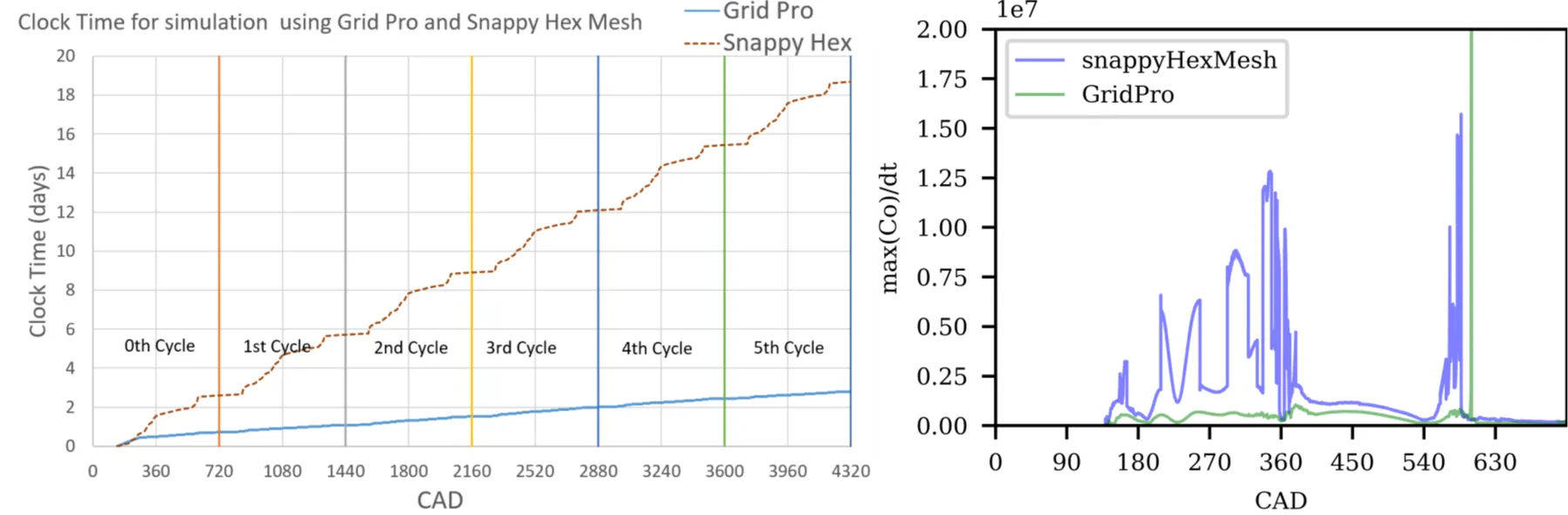
That is a one-million-cell difference. But cell count is only half the story. The real win is in the Courant number (Co). This is the mathematical limit on how big of a time-step your high fidelity IC engine CFD simulation can take. Because GridPro’s cells are higher quality and avoid the “stair-stepping” artifacts of unstructured grids, it can run with much larger time-steps.
The study found that the ratio of max(Co)/dt—a measure of how much a mesh slows down the clock—was significantly lower for GridPro. The wall-clock time for a 5-cycle simulation was dramatically shorter on the structured grid. “Computational speed isn’t just about throwing more cores at the problem; it’s about starting with a grid that allows the solver to breathe,” the researchers concluded.
Validation: Matching the PIV Reality
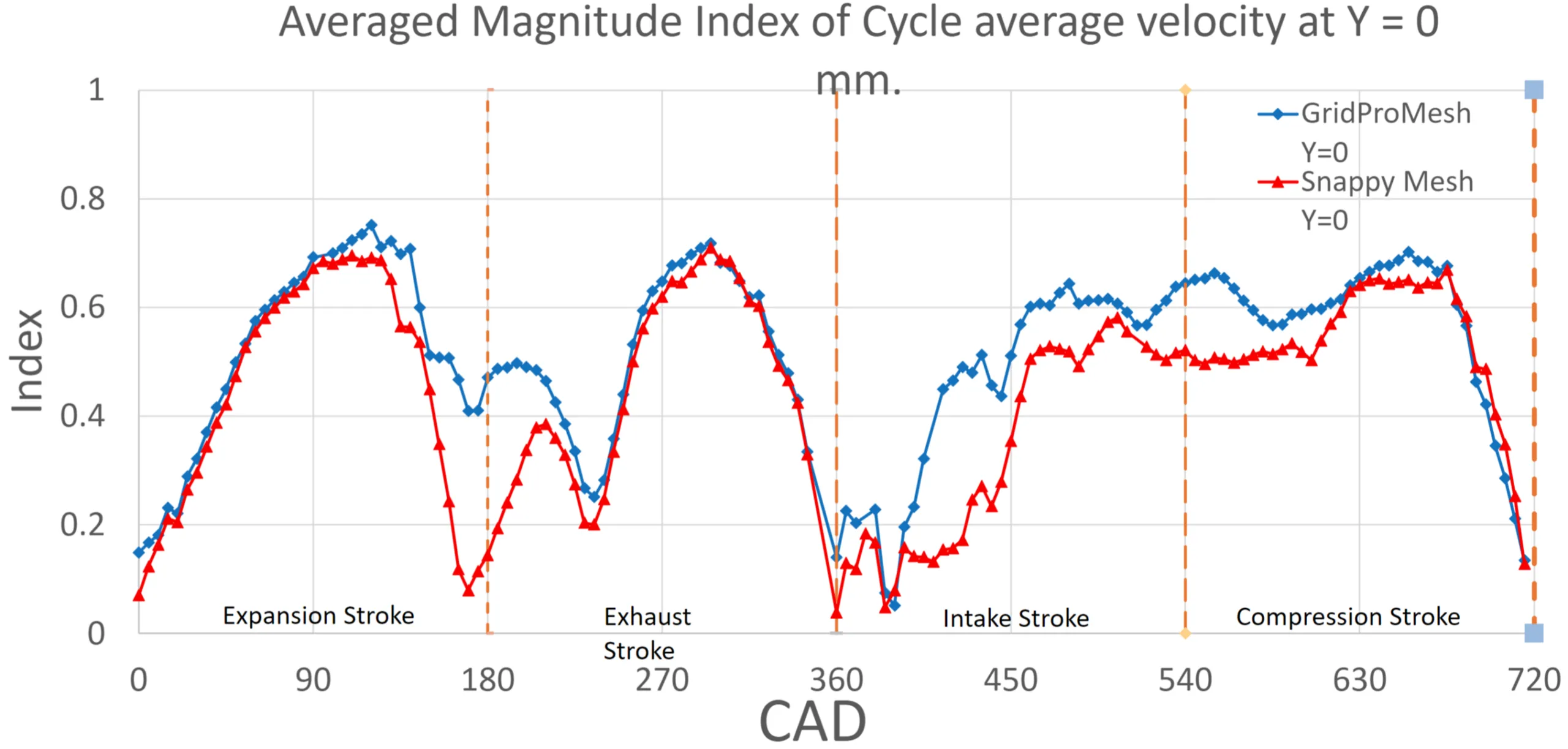
At the end of the day, a fast simulation is worthless if it’s wrong. To verify the results, the team compared the simulated flow fields against experimental Particle Image Velocimetry (PIV) data using two metrics: the Relevance Index (RI) for orientation and the Magnitude Index (MI) for overall vector match.
The structured mesh consistently outperformed the unstructured grid, particularly during the high-velocity intake and exhaust strokes. While both meshes showed “acceptable agreement,” GridPro was much better at capturing the intake jet and the formation of the large-scale vortices.
The pressure traces also confirmed this. GridPro accurately captured the TCC-III’s 10:1 compression ratio (calculated at 9.956:1) and matched the experimental motored pressure curve with a difference of just 0.21 bar at TDC. This level of exactness is exactly what engineers need when trying to predict the sensitive “knock” limits of alternative fuels.
Why Professionals Choose Structured Meshing
Beyond the raw data, the Aalto study highlights a more human benefit: control over complexity. Automated meshers are great until they aren’t. When a “black box” mesher fails to capture a boundary layer or crashes during a valve closing, you have very little recourse.
GridPro gives you the tools to avoid these “refinement traps”. You can define the exact cell distribution needed to capture the physics of a hydrogen intake jet or an ammonia vortex. This stability is vital for multi-cycle simulations where small errors can compound over thousands of time-steps.
And for those worried about the “manual labor” of structured meshing, the future is already here. The Aalto team successfully automated the entire workflow—from geometry preparation to post-processing—using Python and bash scripts. This creates a high-performance, “plug-and-play” environment that combines the speed of automation with the exactness of structured grids.
Conclusion: The Verdict for Future IC Engines
The TCC-III benchmarking study is more than just a software comparison; it is a roadmap for the next decade of engine development. As we ask internal combustion engines to do more with less—and to run on fuels we are still trying to understand—the quality of our grids has never been more important.
The verdict is in: structured, body-conformed meshing is the way forward. It provides the detail required for high-fidelity modeling, the resilience needed for complex mesh motion, and the efficiency required to meet tight deadlines. By moving away from the “easy” unstructured path and embracing the power of multi-block grids, the CFD community can accelerate the transition to a sustainable, carbon-free future.
Further Reading
- Piston Bowl Design Optimization and Meshing for CFD
- Role of CFD in Efficient Design of Fuel Injectors
- Shape Optimization for CFD-101
References
- “Simulation and validation of an internal combustion engine under motored condition using OpenFOAM“, Bishal Shrestha, Master’s Thesis 2023, Aalto University School of Engineering.
- “RANS simulation and validation of full-scale internal combustion engine under motored condition.“, Bishal Shrestha, MSc(Tech). School of Engineering, Aalto University, 11th March 2024.