
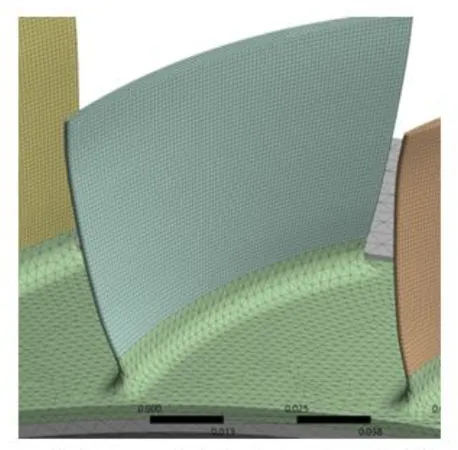
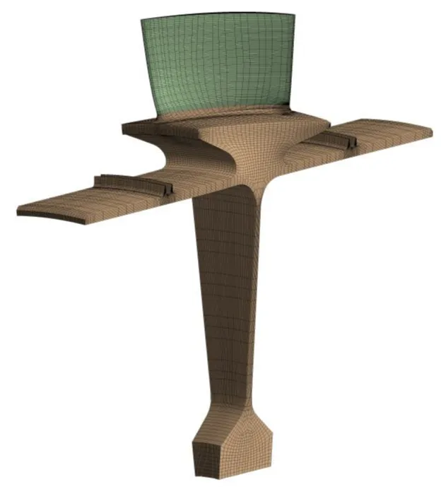
Figure 1: Structured hexahedral mesh for turbine blade vibration analysis.
1440 words/ 7 mins read
High Cycle Fatigue causes 55% of major jet engine accidents. For FEA engineers, precision is the only defense. While unstructured hybrid grids struggle with complex fillets, automated structured hexahedral meshing accurately captures the critical stress spikes triggered by mistuning. Don’t let discretization errors compromise your safety analysis.
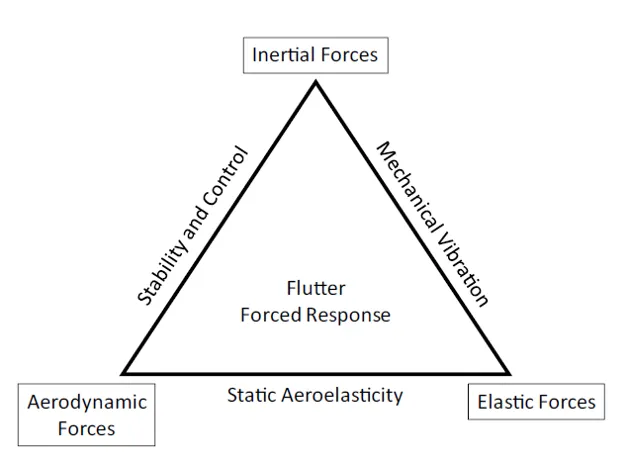
In the high-stakes environment of turbomachinery design, the margin for error is razor-thin. When an integrally bladed rotor (IBR), or blisk, operates at design speeds, it faces a complex array of inertial, elastic, and aerodynamic forces. While thermal management often takes center stage, the silent killer of turbine components is High Cycle Fatigue (HCF). Research indicates that HCF is responsible for approximately 55% of Class A jet engine accidents—those resulting in over $1 million in damages or the total loss of the aircraft.
For FEA and CFD engineers, the challenge lies in predicting these failures during the design phase. We utilize Finite Element Method (FEM) simulations to anticipate how a rotor will respond to periodic aerodynamic loading. However, the reliability of these simulations is not merely a product of the solver’s complexity; it is fundamentally rooted in the quality of the discretization. As we explore the dynamics of mistuned rotors, it becomes increasingly clear that structured, multi-block hexahedral meshing is a technical requirement for capturing the physics of mode localization and resonant response.
The Aeromechanical Reality: Forced Response and Mistuning
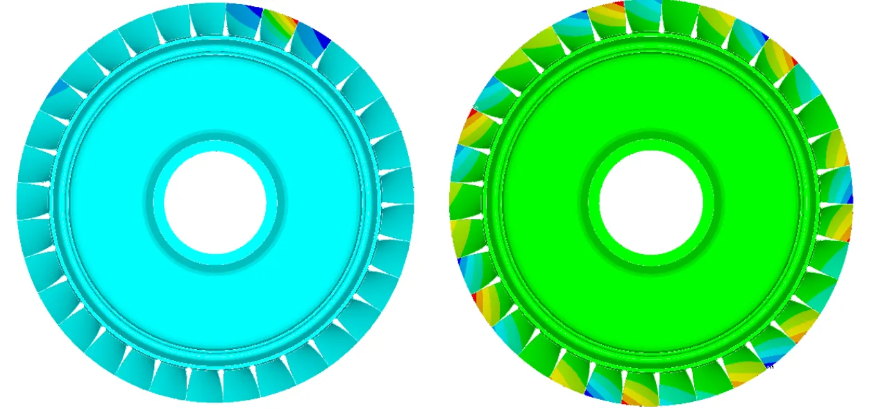
To understand the necessity of high-fidelity meshing, we must first address the phenomenon of mistuning. In a theoretical “tuned” system, every blade on a rotor is identical in geometry and material properties. In such a system, cyclic symmetry allows us to model a single sector to predict the behavior of the entire disk, significantly reducing computational overhead.
However, real-world rotors are never perfectly periodic. Small variations in manufacturing tolerances, non-uniform wear, and material inconsistencies introduce mistuning. While these deviations may seem negligible, they destroy the cyclic symmetry of the system and lead to mode localization. In a localized state, vibration energy that should be distributed across the entire rotor becomes confined to a small subset of blades. This confinement leads to stress amplifications that can exceed tuned predictions by 20% or more, even with manufacturing deviations as low as 0.1%.
The Limitations of Hybrid and Unstructured Meshing
When engineers approach the simulation of complex geometries like the Purdue 3-Stage Axial Compressor’s Rotor 2, the choice of discretization strategy is critical. While many workflows utilize unstructured or hybrid meshing due to their perceived ease of setup, these approaches have inherent technical limitations when applied to precision vibration analysis.
Unstructured and hybrid strategies often struggle with the following areas in turbomachinery:
- Geometric Fidelity in Transition Zones: In a recent study on Rotor 2, researchers found that commercial unstructured meshers often fail to maintain high element quality in complex transition zones, such as the root-hub fillets. To compensate, these tools often revert to tetrahedral discretization in these curved regions.
- The Bonded Contact Problem: Because unstructured meshers may struggle to create a continuous, sweepable mesh across a complex blisk, engineers are often forced to split the geometry into multiple bodies—the blade, hub, and root. This necessitates the use of bonded contacts to reconnect the mesh. In modal analysis, these interfaces can introduce artificial stiffness or numerical discontinuities, leading to significant discrepancies in tuned frequencies.
- Cyclic Match Control: For IBRs, maintaining a perfectly conformal mesh across periodic boundaries is mandatory. Many unstructured approaches struggle to ensure that the nodes on the “high” and “low” periodic faces match perfectly while simultaneously handling the internal complexity of the blade. Any non-conformality here introduces “numerical mistuning” that pollutes the modal base.
The Technical Advantage of Structured Hexahedral Topologies
The alternative to unstructured volumetric filling is the development of a structured multi-block hexahedral topology. For a professional analyst, the move to purely hexahedral elements provides several physical and mathematical advantages:
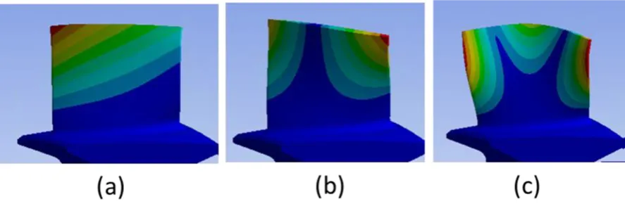
- Alignment with Strain Energy Paths: Vibration modes, particularly the First Bending (1B) and First Torsion (1T) families, follow the structural flow of the blade. Hexahedral elements naturally align with these stress paths, capturing the strain energy with far greater precision than tetrahedral elements.
- Superior Convergence with Fewer DOF: Tetrahedral elements are notoriously stiff in bending-dominated modes. Achieving an accurate solution with tetrahedrons requires an exponentially higher element count, which increases the degrees of freedom (DOF) and computational cost. Structured hexahedral meshes reach an asymptotic solution—often within a 2% error margin—using significantly fewer equations.
- Resolving “Veering” Regions: Turbine rotors frequently operate in veering regions where different vibration mode families approach each other and exchange energy. Capturing the response in these high-modal-density regions requires a mesh that does not introduce numerical noise. The Purdue study showed that only high-quality structured models could capture the intricate energy exchanges between the disk and blades in these regions.
Breaking the Myth: Automation in Structured Meshing
A common misconception in the industry is that structured meshing is a manual, labor-intensive process, while unstructured meshing is “automated.” In reality, automation can be achieved in structured multi-block meshing as well.
The latest advancements in specialized tools, such as those from GridPro, have transformed the workflow. Newer GridPro tools now facilitate the automated multi-block meshing of turbine blades. This allows engineers to enjoy the high accuracy of a structured hexahedral mesh without the traditional time-consuming manual setup. By defining a sophisticated topology once, the tool can automatically generate high-fidelity, purely hexahedral meshes across different blade geometries or design iterations.
In the Purdue Rotor 2 research, this structured approach was essential for solving the accuracy issues encountered with hybrid grids. GridPro enabled the creation of a structured mesh with 10.90909 degrees periodicity that perfectly matched the CAD geometry at every node. This level of precision was so high that it revealed “inherent mistuning” caused by the mesh itself, allowing the researchers to account for it and ensure a perfectly tuned benchmark.
Reduced Order Modeling (ROM) and Mesh Dependency
Because full-blisk FEM models are computationally expensive, engineers rely on Reduced Order Models (ROMs) such as Component Mode Mistuning (CMM) and Fundamental Mode Mistuning (FMM).
A ROM is only as accurate as the modal base it is built upon.
- CMM Performance: The CMM method requires an accurate set of Tuned System Modes (TSM) and Cantilever Blade Modes (CBM). The study demonstrated that when a high-quality structured mesh is used, CMM can predict the forced response of a mistuned system within a 2% error margin across the entire frequency sweep.
- FMM Sensitivity: While the FMM model is useful for preliminary design and isolated mode families, it is extremely sensitive to frequency selection and discretization quality in veering regions. To rely on FMM, the underlying mesh must be precise enough to verify that the mode family is truly isolated and not polluted by disk-dominated interactions.
The Path to Predictive Engineering
At its core, FEA is about building trust in your data. If your discretization strategy relies on a hybrid mesh that underestimates mode localization, you might approve a design that is at risk of a catastrophic HCF failure.
The transition from unstructured/hybrid meshes to automated structured multi-block meshing represents a shift toward more reliable engineering. By using tools like GridPro, analysts can:
- Discretize complex fillets and hubs with pure hexahedral elements, eliminating the need for tetrahedral elements.
- Maintain perfect cyclic symmetry without using bonded contact interfaces that introduce artificial stiffness.
- Generate a high-fidelity modal base that allows ROMs like CMM to converge rapidly and accurately.
For the Purdue researchers, moving to a structured hexahedral workflow was the only way to correctly predict how the rotor would respond in the real world. For the next generation of FEA and CFD engineers, mastering these structured techniques is the mark of a specialist who understands the deep link between the mesh and the physical integrity of the engine. By choosing the right discretization and the right tools, we can ensure that every engine we design is built on a foundation of accuracy, turning the risks of HCF into a controlled and understood variable of the design process.
Further Reading
- Meshing for Tip Gaps and Leakage Flows in Turbomachinery CFD
- Automated Hexahedral Meshing with GridPro: Structured Meshes for Parametric Geometry Variants
- Effective Control of Turbine Blade Tip Vortices Using Squealer Tips
Reference
“Reduced Order Modelling Of Mistuned Integrally Bladed Rotors“, Jhansi Reddy Dodda, MS Thesis, Purdue University, August 2023.