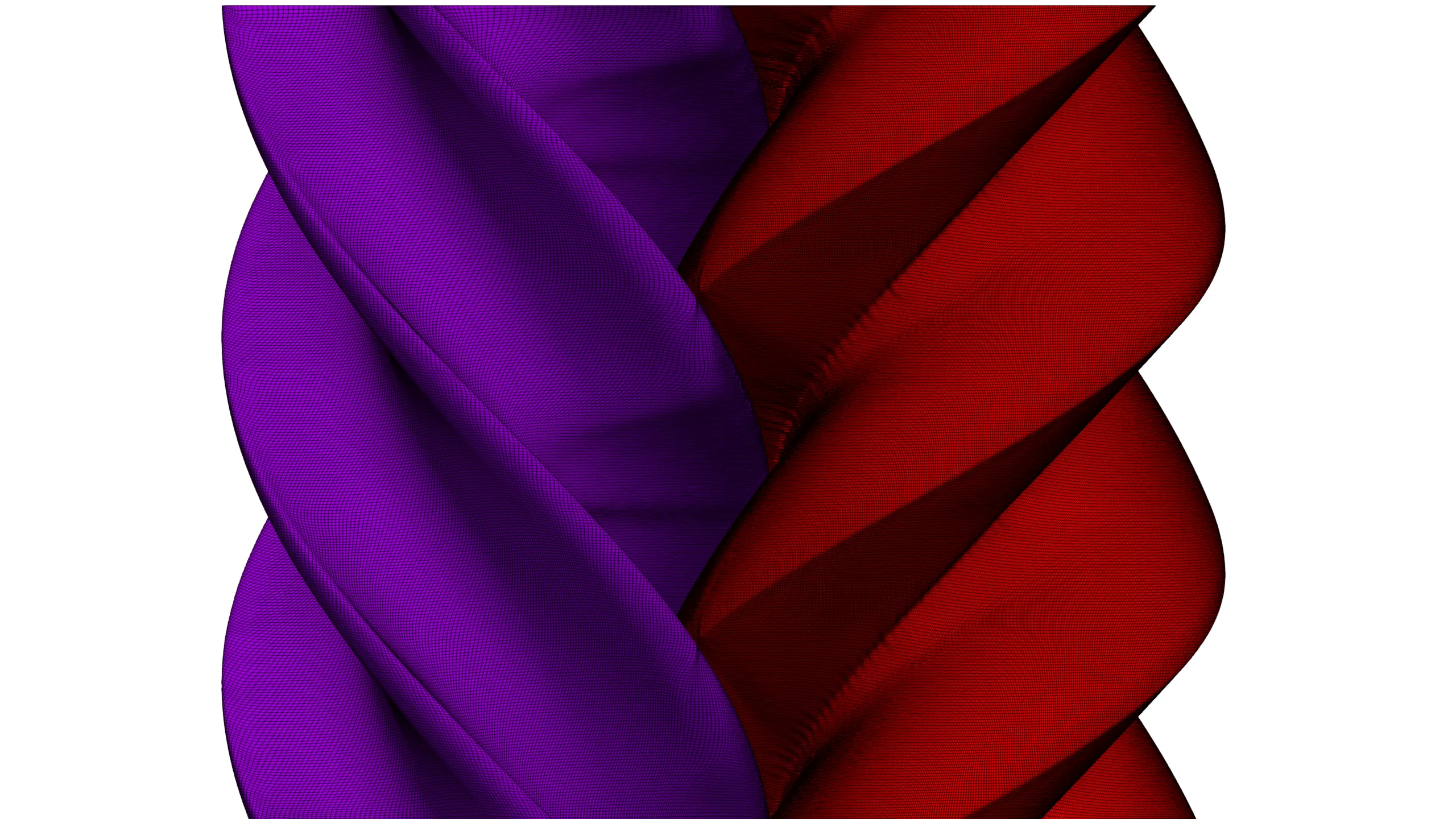
Figure 1: Hexahedral mesh for accurate capturing of leakage gaps in screw compressors.
1106 words / 6 minutes read
Leakage flows stand out as the primary factor leading to decreased efficiency within screw compressors. Precisely capturing these leakage flows using enhanced grids plays a crucial role in achieving precise CFD predictions of their behavior and their consequential impact on the overall performance of the screw compressor.
Need for Understanding Leakage Flows
Rotating volumetric machines like screw compressors or tooth compressors are used extensively in many industrial applications. It is reported that nearly 15 percent of all-electric energy produced is used for powering compressors. Even a small improvement in the efficiency of these rotary compressors will result in a significant reduction in energy consumption. In fact, a small variation in rotor shape hardly visible to the naked eye can cause a notable change in efficiency.
Research indicates that the primary factor leading to efficiency reductions in screw compressors is leakage. This leakage occurs as a result of gaps present between rotors and between rotors and the casing. Among various thermo-fluid behaviours, internal leakage has a more substantial impact, particularly when operating at lower speeds and higher pressure ratios.
With improvement in energy efficiency becoming the main objective of design and development teams, there is a growing interest in flow patterns within screw compressors, particularly focusing on the phenomenon of leakage flows.
Why is CFD the Preferred Tool for Leakage Studies?
Screw compressors operate by altering the volume of the compression chamber, leading to corresponding variations in internal pressure and temperature. As pressure builds up during compression, the compressed gas seeks to move into lower-pressure chambers through the leakage gaps.
Unfortunately, due to the helical nature of the compression process in positive displacement machines, it is very difficult to visually appreciate this leakage flow by any experimental methods. Also, the complex flows in screw compressors demand more detailed studies, which makes conducting physical experimentation very expensive. Hence, experimental studies in these machines have become less attractive, while CFD, with accurate prediction abilities along with detailed 3D flow measurement and visualization capabilities, has been accepted as the workable alternative.
The Leakage Paths
In positive displacement machines, leakage flow is an inescapable devil. Due to the nature of the mating parts and the need for clearances between them, the compressor is bound to have several leakage paths. About 6 different leakage paths have been identified, as shown in Figure 2.
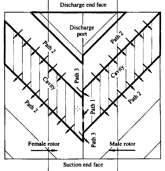
Out of these, only the cusp blow holes have a constant geometry, while the rest of the paths have a geometry and flow resistance that varies periodically in a way unique to each individual path. Further, the pressure difference driving the fluid along a leakage path also varies periodically in a manner that is unique to each leakage path.
Leakages can broadly be categorized into two groups. In the first kind, the leakage happens from the enclosed cavity or discharge chamber to the suction chamber. This causes a reduction in both volumetric and indicated efficiencies. While in the second group, leakage flow occurs from the enclosed cavity or the discharge chamber to the following enclosed cavity. Although the indicated efficiency reduces in this mode, the volumetric efficiency does not.
Each leakage path uniquely influences the performance of the compressor. Hence, it is important to understand the attributes of the leakage through each leakage path and the percentage by which it can impact the machine’s efficiency. This is essential because it helps prioritise the design procedures in general and specifically enhancing the rotor lobe profile.
Importance of Accurate Capturing of the Leakage Gaps in Screw Compressors by Grids

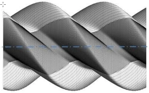
The critical factor which affects the CFD performance prediction of twin screw compressors is the accuracy with which leakage gaps are captured by gridding strategies. Since the working chamber of a screw machine is transient in nature, we need a grid that could accurately represent the domain deformation.
One approach is simply increasing the grid points on the rotor profile. Studies have shown that grid refinement in the circumferential direction directly influences mass flow rate prediction. In contrast, it has a lesser influence on predicting pressure and power. However, since we want to do a transient simulation in a deforming domain, this gridding approach will cause quicker deterioration in grid quality and a rapid rise in computational time.
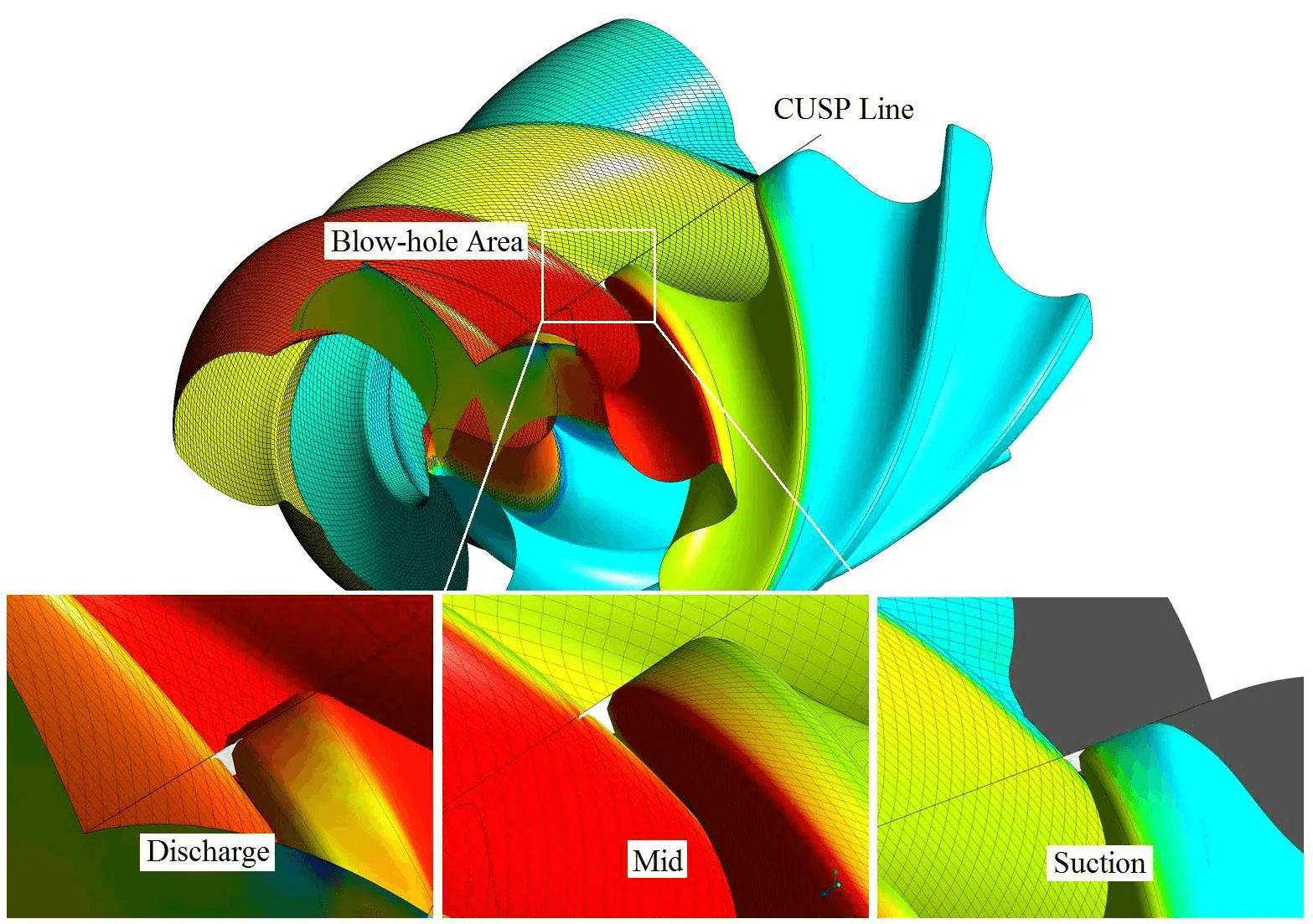
Alternatively, another effective way to tackle this discretization challenge is to locally refine only the interlobe space region. This particular area holds utmost significance in managing leakage flows. By confining the increase in cell count to the interlobe gaps and blow-hole areas, the overall grid dimensions can be maintained under control.
The benefits of mesh refinement in the vicinity of interlobe gap and blow-hole area can be seen in improved accuracy in predicting mass flow rate and leakage flows. Interlobe refinement improves the curvature capturing of rotor profiles and also the mesh quality. This is reflected in the CFD predictions.
Positive Effects of Interlobe Grid Refinement
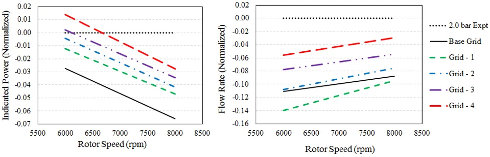
The difference between experimental indicated power and CFD predictions on the base grid is about 2.7% at 6000 rpm and 6.6% at 8000 rpm. With interlobe grid refinement, the difference reduces to 1.4% at 6000 rpm and 2.8% at 8000 rpm.
The enhancement of the interlobe grid refinement significantly impacts the flow rate. The contrast between experimental outcomes and CFD projections on the base grid is noticeable, registering at 11% and 8.7% for 6000 rpm and 8000 rpm respectively. These disparities decrease notably to approximately 5.5% and 2.9% following grid refinement.
The volumetric efficiency prediction on the base grid is 7% lower than the experiment. With refinement, the difference reduces to 3%. As with other variables, the difference is smaller at 8000 rpm than at 6000 rpm.
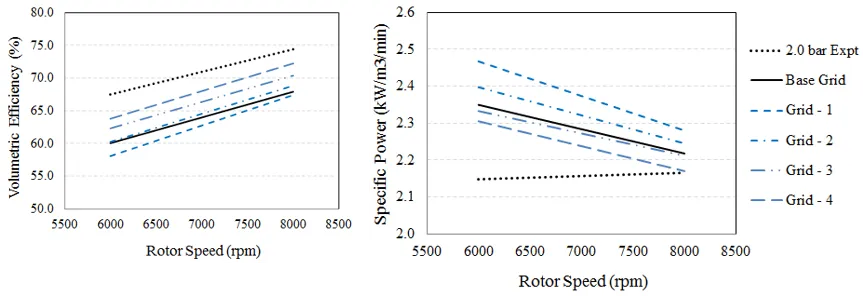
Specific indicated power, reliant on indicated power and mass flow rate, displays sensitivity. At 6000 rpm, the difference between the base grid CFD prediction and experimental-specific indicated power is about 0.2 kW/m3/min, which reduces to 0.15 kW/m3/min with refinement. At 8000 rpm, the CFD predictions match with the experiment, as can be seen in Figure 7.
To Sum Up
The findings suggest that employing finer grids leads to better capturing of the rotor geometry, thereby enhancing the accuracy of leakage loss representation. With successively refined grids, the reduction in leakage losses becomes apparent. As a result, the CFD predictions gradually align more closely with experimental data.
Further Reading
1. Challenges in Meshing Scroll Compressors
2. Automation of Hexahedral Meshing for Scroll Compressors
3. The Art and Science of Meshing Turbine Blades
References:
1.“The Analysis of Leakage in a Twin Screw Compressor and its Application to Performance Improvement”, John Fleming et al., Proc Instn Mcch Engrs Vol 209, 1995.
2. “Analytical Grid Generation for accurate representation of clearances in CFD for Screw Machines”, S Rane et al., Article in British Food Journal · August 2015.
3. “Grid Generation and CFD Analysis of Variable Geometry Screw Machines”, Sham Ramchandra Rane, PhD Thesis, City University London School of Mathematics, Computer Science and Engineering August 2015.
4. “ CFD Simulations of Single- and Twin-Screw Machines with OpenFOAM”, Nicola Casari et al., Designs 2020.
5. “Numerical Modelling and Experimental Validation of Twin-Screw Expanders” Kisorthman Vimalakanthan et al., Energies 2020, 13, 4700.
6. “New insights in twin screw expander performance for small scale ORC systems from 3D CFD Analysis”, Iva Papes et al., Journal of Applied Thermal Engineering, July 15, 2015.
7. “A GRID GENERATOR FOR FLOW CALCULATIONS IN ROTARY VOLUMETRIC COMPRESSORS”, John Vande Voorde et al., European Congress on Computational Methods in Applied Sciences and Engineering, ECCOMAS 2004.
8. “CFD SIMULATION OF A TWIN SCREW EXPANDER INCLUDING LEAKAGE FLOWS”, Rainer ANDRES et al., 23rd International Compressor Engineering Conference at Purdue, July 11-14, 2016.
9. “Calculation of clearances in twin screw compressors”, Ermin Husak et al., International Conference on Compressors and their Systems 2019.