
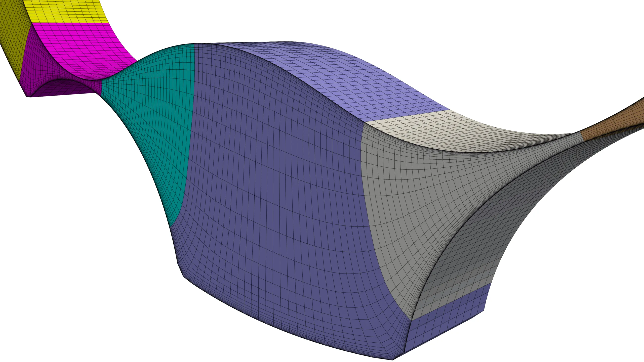
Figure 1: Automated gerotor pump meshing with GridPro’s structured multiblock grid generator.
1454 words / 7 minutes read
Automated hexahedral mesher empowers engineers to effortlessly scrutinize the flow behaviour, vividly understand the change in flow with the change in clearance gap, and explicitly bring out the differences in the gerotor design variant’s performances.
Introduction
The unique characteristics of gerotor pumps have made them a widely used pumping device in various industries. They are compact, reliable, and inexpensive, making them a cost-effective option for fluid transfer applications.
Additionally, they offer high tolerance to fluid contamination, aeration, and cavitation. By providing excellent flow control, minimal flow pulsation and low noise, they have a strong footprint in the aerospace, automotive and manufacturing sectors.
The aerospace industry uses them for cooling, lubrication, and fuel boost and transfer processes. In manufacturing, they are used for dosing, filling, dispensing, and coating applications.
Gerotor pumps are also extensively used in the automotive, agriculture, and construction fields, particularly for low-pressure applications. With the progress of technology, gerotor pumps are finding new applications in the life science, industrial, and mechanical engineering sectors.
Driving Forces for Gerotor Pump Research
This expansion in applicability across various industries is driving the gerotor pump research for further improvement. Also, the growing environmental concern in various industries is creating a need for newer applications, which demand pumps that can improve their efficiency.
Gerotor pumps, with their simple design, have presented themselves as an attractive option for these newer applications. However, the increasing demand for pumps that meet stringent specifications and shorter design cycles necessitates a cost-effective design process that can lead to optimal performance and efficiency.
This has driven further research on gerotor pumps, focusing on improving design through numerical simulation. This allows designers to identify potential performance issues and optimize their designs before building physical prototypes.
By leveraging this approach, researchers are leading the way towards more efficient and reliable gerotor pump designs that meet the growing demand for pump applications in various industries.
CFD in Gerotor Pump Design: Advantages and Constraints
CFD is an essential tool for the design and optimization of gerotor pumps. CFD simulations accurately predict the effect of cavitation and fluid-body interaction on performance by providing a detailed description of the fluid’s behaviour inside the pump. Due to its accuracy, CFD is often used as a benchmark for pump experiments when no experimental comparison data is available.
However, there are certain challenges in using CFD for gerotor pump design. The CFD process requires large simulation time and memory requirements, and there is a need to re-mesh the entire domain at each angular step. Further, meshing the inter-teeth clearance and constantly changing fluid domain could be a challenging task.
These constraints can delay the design verification stage, making the process time-consuming. The design engineer must mesh the volume chambers each time the design changes and perform a time-consuming simulation. In most cases, the simulation of a geometric configuration takes up to a day to generate results. This workflow hinders the effectiveness of rapid design methodologies or the easy testing of a large number of geometric configurations of the pump in a reasonable time.
Gerotor Pump Meshing Challenge
The primary focus of research w.r.t meshing positive displacement machines is the development of methodologies to support rapid simulation of any geometry. Efforts are made to develop meshing methods to automatically generate high-resolution grids with optimal cell size and high quality without human intervention.
However, gerotor pump meshing is challenging due to the rotating and deforming fluid volumes created during their working cycle. The rapid transformation of the deforming fluid zone from a large pocket region to a narrow passage makes meshing extremely difficult, w.r.t maintaining cell resolution, cell quality and mesh size. Trying to attain one of these meshing objectives results in the failure of the other. On top of this, coming up with a meshing procedure to avoid human intervention further ups the difficulty levels.
Additionally, the tight clearance space, which plays a significant role in determining volumetric efficiency, presents another obstacle for CFD simulations. These clearances are extremely small, often in the range of a few microns, and impact various aspects of the pump’s performance, such as flow leakage, flow ripple, cavitation, pressure lock, torque, and power. Out of these, the flow ripple parameter is significantly affected by the design of the tip and side gaps. A high ripple in the outlet flow can cause high levels of vibration and noise in the pump.
Hence it is critically important to accurately represent these narrow gaps with high-resolution, high-quality meshes to bring out their effects in high clarity. Low-resolution coarse grids will decrease the accuracy and may lead to over or underestimation of the flow variables. Maintaining a certain mesh quality is also important, as it enables CFD to easily analyse variations in clearances and other tendencies.
Commonly Adopted Meshing Techniques
Various meshing techniques have been employed over time to discretize the gerotor fluid space. Among them, overlapping meshing methods, deform and remesh methods and customised structured meshing are the most popular ones.
Overlapping meshing methods, including the overset and immersed boundary methods, are frequently used. Although they are quick to generate, they often fall short of properly resolving the boundary layer and narrow clearance gaps while also employing an excessive number of cells.
The deform and remesh method is another popular approach that offers automation but often generates grids with a large cell count. Unfortunately, these methods can cause interpolation errors and stability issues while running the CFD solvers.
While manual customised grid generation methods provide the best mesh in terms of cell quality and grid size, they demand excessive time and human effort to generate the mesh. Unlike the generic moving mesh methods, such as the immersed boundary method, manual gridding approaches, such as the structured moving/sliding methods, accurately represent the dynamic gaps.
Structured Moving/sliding mesh approach
In the structured moving/sliding mesh approach, the fluid volume of the rotor chamber is isolated from the stationary fluid volumes related to the suction and delivery port. The rotor volume is topologically similar to a ring, making it easy to create an initial structured mesh for this shape. This zone being an extrudable domain, a 2D grid is created, which is later extruded to get a 3D mesh.
The stationary fluid volumes of the suction and delivery port are meshed using unstructured approaches. They are linked to the rotor mesh volume via non-conformal interfaces.
When the inner gear surface shifts to a new position, the mesh on the surface does not simply move with it. Instead, the mesh “slides” on the inner gear surface while adjusting to conform to the new clearance between the inner and outer gear surfaces. Simultaneously, the interface connections between the rotor volume and other fluid volumes are updated. These meshing steps ensure good resolution of the clearance space while maintaining good cell quality.
Single Topology Approach of GridPro
GridPro addresses the gerotor pump meshing challenge with its unique single-topology multi-configuration approach. To start with, for a given instance of the inner and the outer gear position, a 2D wireframe topology is built. Since the meshing zone is 2.5D in nature, a grid in 2D is good enough, which is later extruded in the perpendicular direction to get the 3D grid. The 2D topology acts as a template, to be later used repeatedly to generate mesh for all instances of the inner and outer gear positioning.
An automated python script ensures the grids for all angular steps are generated in an automated, hands-free environment. The script rotates the inner and outer gear at a user-specified angular step of 0.1 degrees and gives out a grid with consistent mesh quality. Since the topology is the same, the mesh generated for each angular step is practically the same. This particular aspect brings in significant positive benefits when compared to an unstructured re-meshing approach where the cell count and connectivity are completely different from one angular step grid to another.
This consistency in grids generated for all instances of the gear position aids in generating superior flow field simulation results. The automated meshing environment saves time and human effort and provides the much-needed trust of the design engineer in the simulated CFD data.
Conclusion
Engineers can enhance their workflow for 3D CFD analyses of gerotor pumps with an automated hexahedral mesher. It will empower engineers to effortlessly scrutinize the flow behaviour inside the working chambers, vividly understand the change in flow physics with variation in clearance gap, and explicitly bring out the differences in parametric design variant’s performances.
More importantly, an automated mesher brings the engineers’ focus back to the design aspects of the pump rather than on the meshing.
Further Reading
- Automation of Hexahedral Meshing for Scroll Compressors
- Turbopumps – A Unique Rotating Machine
- Efficient Meshing of Turbine Blade Cooling Holes!
- The Importance of Flow Alignment of Mesh
Reference
- “A Study on Effect of Operating Conditions on Gerotor Pump Performance”, Tarique Hussain et al., Defence Science Journal, Vol. 72, No. 2, March 2022, pp. 146-150.
- “A CFD-Based Comparison of Different Positive Displacement Pumps for Application in Future Automatic Transmission Systems”, Thomas Lobsinger et al., Energies 2021, 14, 2501.
- “A CFD model for orbital gerotor motor”, H Ding et al., 26th IAHR Symposium on Hydraulic Machinery and Systems, 2012.
- “Computational fluid dynamics and particle image velocimetry assisted design tools for a new generation of trochoidal gear pumps”, M Garcia-Vilchez et al., Advances in Mechanical Engineering, 2015, Vol. 7(7).
- “A Virtual Prototype for Fast Design and Visualization of Gerotor Pumps“, Juan Pareja-Corcho et al , Applied. Sciences. 2021, 11, 1190.
- “Three Dimensional Simulation of Gerotor with Deforming Mesh by using OpenFOAM”, Robert Castilla et al, Universitat Politècnica de Catalunya, LABSON Department of Fluid Mechanics, Colom, 11, ES-08222 Terrassa, Spain.