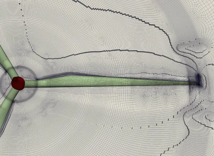
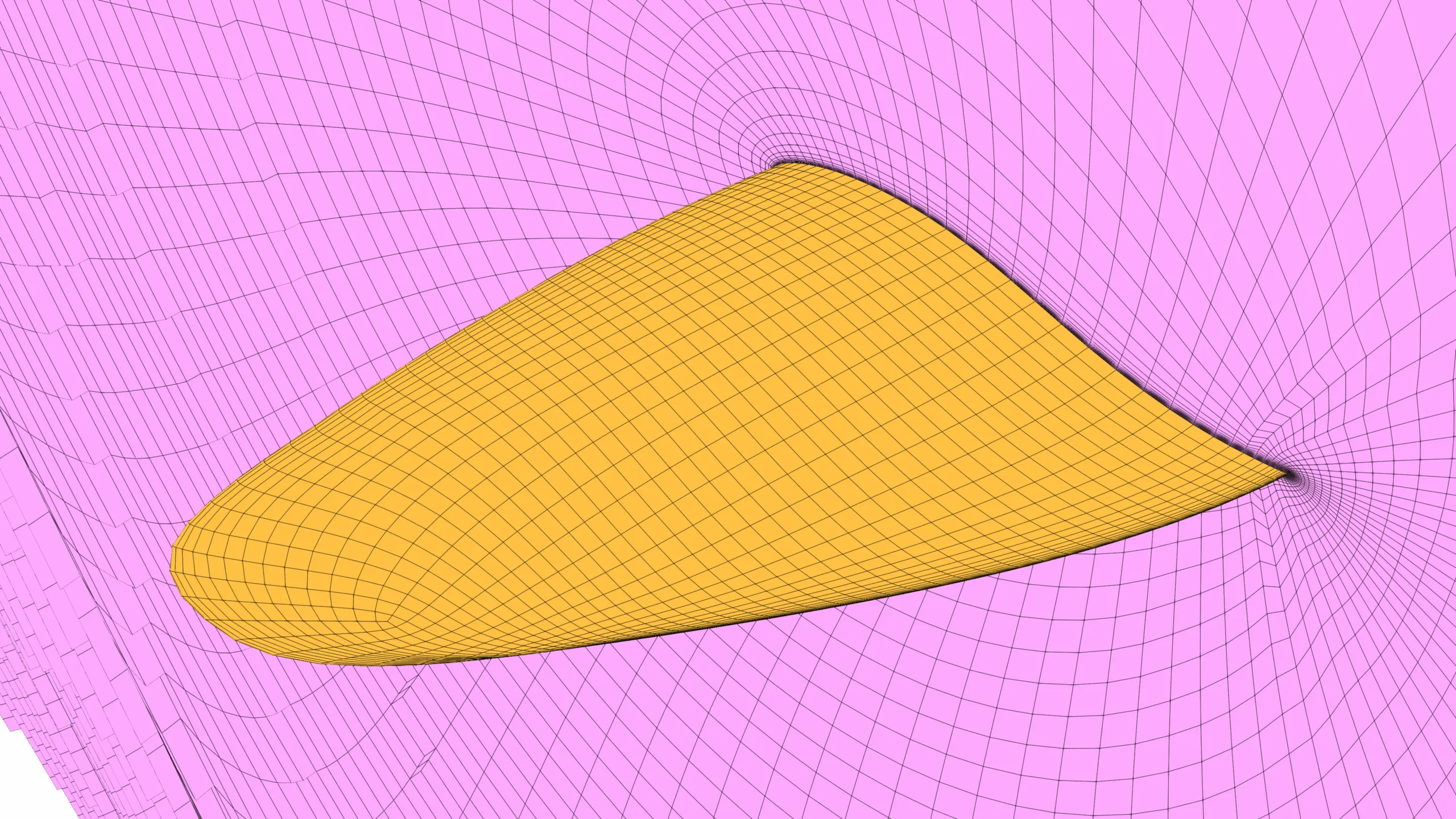
Figure 1: Structured mesh for wind turbine blades CFD simulation.
Word count: 1724 / 9 min read
Behind every accurate wind-turbine CFD simulation lies one secret ingredient — the mesh. It shapes how air, pressure, and turbulence are understood by your solver. From blade-root complexity to tip vortices, structured multi-block meshes reveal the physics others miss — proving that in CFD, mesh defines the math — and the outcome.
Introduction
Ever wondered why some CFD simulations for wind turbine blades converge beautifully, while others drag on for days and still struggle to stabilise? The difference often lies not in the solver or turbulence model — but in the mesh.
In computational fluid dynamics, the mesh is more than a discretisation step; it’s the invisible architecture that determines how faithfully your solver captures aerodynamic reality. For wind turbines, where efficiency, torque, and wake behaviour drive performance, the blade mesh becomes the foundation on which every result depends.
This post explores how CFD meshes are built for modern wind turbine blades — why structured, multi-block grids continue to outperform unstructured ones — and how multi-block structured meshing workflows help engineers balance accuracy, efficiency, and scalability.
Why Blade Meshing Is the Most Critical Step in Wind Turbine CFD
In wind turbine simulations, the blade mesh is the foundation of aerodynamic accuracy. Every physical process — lift, drag, torque, and wake formation — begins at the blade. If that geometry is poorly represented, even the most advanced solver cannot recover the missing physics.
A turbine blade presents meshing challenges unlike any other aerodynamic surface. It twists, tapers, and curves along its span, with rapidly changing pressure gradients from root to tip. A good mesh must capture these variations smoothly, maintaining orthogonality and controlled growth rates. Misaligned or stretched cells distort gradients, leading to lift and pressure errors that cascade downstream.
Research studies have demonstrated that multi-block structured meshes significantly improve residual convergence and pressure recovery around wind turbine blades. By aligning cells with the flow and maintaining smooth transitions across blocks, structured meshes reduce numerical diffusion and deliver more stable results. In other words, the mesh doesn’t just describe the geometry — it defines how the solver “sees” the physics.
Blade Governs Lift, Drag, and Wake Onset — Performance Originates Here
The aerodynamic performance of a turbine originates entirely at the blade surface. Lift arises from the pressure difference between suction and pressure sides, while viscous drag builds within the boundary layer. The resulting wake pattern determines how efficiently the turbine extracts energy and how it affects downstream rotors.
To predict this behavior accurately, the mesh must align with chordwise and spanwise flow directions, allowing the solver to resolve gradients along the same paths as the air. Misaligned or skewed elements introduce cross-flow diffusion that can shift lift and drag predictions by several percent — a critical error in design optimization. Structured, flow-aligned grids eliminate this uncertainty and maintain stable wake resolution across operating conditions.
Why Surface Resolution Drives Accuracy More Than Solver Choice
Solver capability matters, but surface resolution often matters more. The solver can only calculate gradients based on the mesh it’s given. Capturing the thin boundary layer requires precise control of wall spacing to maintain y⁺ < 1 for RANS or LES simulations. Structured or multi-block grids make that control practical and repeatable.
A research study has found that refining near-wall spacing improved lift prediction by over 7%, whereas changing solvers affected accuracy by less than 2%. The lesson is clear: in wind turbine CFD, the mesh doesn’t support the solver — it empowers it.
Structured vs Unstructured Meshing — Practical Differences
In CFD for wind turbines, the debate between structured and unstructured meshing is less about preference and more about purpose. Both can model complex geometric forms, but their differences in accuracy, computational effectiveness, and ease of generation determine which one wins in practice.
Structured meshes are like an ordered lattice — every cell has a predictable neighbor, creating a logical grid. Unstructured meshes, by contrast, resemble a mosaic — flexible and automatic but less uniform. Each has strengths, but for wind turbine blades, where flow alignment and boundary-layer accuracy dominate, structure still leads.
Where Structured Grids Outperform Unstructured on Turbine Blades
Structured grids shine when exactness and stability are non-negotiable. Their ordered connectivity lets solvers compute gradients efficiently, improving convergence and reducing RAM overhead. For turbine blades, structured meshes can align with the chordwise and spanwise flow directions, reducing numerical diffusion and ensuring that pressure and velocity gradients remain physically consistent.
According to meshing study, structured meshes provide superior wake resolution and boundary-layer capture compared to unstructured alternatives. They also produce cleaner surface pressure distributions, leading to more accurate lift and torque predictions — essential for blade optimization and aeroelastic analysis.
In rotating reference frames, structured meshes maintain better continuity across sliding interfaces, keeping wake behavior stable during transient runs. For these reasons, structured grids are still the standard for final design validation in wind turbine aerodynamics.
When Unstructured Meshing Is “Good Enough” for Industrial Turnaround Time
Unstructured meshing earns its place in early-stage design. It handles complex geometry automatically and dramatically reduces setup time. Engineers frequently depend on it for parametric sweeps or concept evaluations where turnaround matters more than precision.
However, studies have shown that unstructured meshes typically require two to three times more elements to achieve the same near-wall accuracy as structured ones. They’re fast to generate but computationally costlier to run.
Cost vs Accuracy Trade-offs
The choice between structured and unstructured meshing boils down to balancing time and truth. Structured meshes take longer to prepare but pay off with faster solvers and cleaner results. Unstructured meshes are convenient but often over-resolve regions unnecessarily.
In production CFD workflows, engineers increasingly adopt multi-block structured approaches, capturing the accuracy of structured grids without sacrificing usability. The result: faster iteration, stable convergence, and data you can trust — the real measure of CFD success.
Choosing the Right Topology for the Blade (C-grid / O-grid / H-grid)
Once a structured mesh is chosen, topology — how the grid wraps around the blade — becomes the next crucial decision. The topology determines how the mesh conforms to flow features, how well it resolves the boundary layer, and how cleanly it connects across the blade span. For wind turbine CFD, the most common structured topologies are C-grid, O-grid, and H-grid, each tailored to different flow regions and geometric needs.
The ideal topology follows the natural path of the flow. It avoids abrupt cell skewness, preserves orthogonality near the surface, and ensures uniform growth ratios in the wall-normal direction. For most turbine blades, that balance is best achieved using an O-grid around the airfoil surface, transitioning to a block-structured configuration near the hub and tip.
Why O-grid Dominates for Near-Wall Behavior
The O-grid wraps around the blade like a smooth envelope, providing excellent near-wall resolution and consistent spacing from leading to trailing edge. Its circular topology minimizes skewness and supports fine y⁺ control, vital for exact boundary-layer prediction.
According to Peralta et al. (2014), O-grids deliver better pressure recovery and flow stability than C- or H-grids, especially for curved turbine profiles.
Blade Tip Meshing and Avoiding Skewness
At the blade tip, the flow accelerates and rolls into strong vortices. Here, a refined multi-block O-grid or hybrid cap structure keeps cells orthogonal and prevents extreme aspect ratios. This stability allows accurate modeling of tip-losses and wake shedding without numerical artifacts.
Root Region Complexity
Near the root, where the blade meets the hub, geometry transitions become intricate. Multi-block H- or C-grid combinations handle intersecting surfaces and fillets effectively while maintaining structured order. Such topologies ensure smooth continuity between rotating and stationary zones — a key factor in reliable torque and load predictions.
Surface Refinement and y⁺ Targets for Reliable Aerodynamics
Even the best topology needs careful refinement to achieve accurate aerodynamics. For wind turbine blades, surface resolution determines how faithfully the solver captures the boundary layer — where most aerodynamic forces are generated. The goal is to maintain consistent cell growth normal to the wall and keep y⁺ values below 1 for RANS or LES models, ensuring smooth transition from viscous sublayer to outer flow.
Proper refinement avoids under-resolved gradients that distort lift and drag predictions. According to a research study, refining near-wall spacing improves lift prediction by over 7%, underscoring that resolution quality often matters more than solver choice.
Laminar vs Turbulent Meshing Strategies
Laminar regions demand ultra-fine spacing to resolve gentle velocity gradients, while turbulent flows require stable y⁺ control to model shear stresses accurately. Structured meshes excel here by allowing exponential control of wall-normal spacing without introducing skewness.
Transition Modelling Implications
Wind turbines frequently operate in mixed laminar–turbulent regimes. Capturing this transition correctly depends on mesh consistency along the suction surface. Structured O-grid and C-grid layouts preserve smooth growth rates and curvature alignment, enabling transition models to predict separation and reattachment naturally — essential for precise lift and stall prediction.
Future Trends in CFD Meshing for Wind Energy
CFD meshing for wind energy is rapidly evolving toward automation, adaptability, and intelligence. The next generation of tools is expected to use AI-assisted block decomposition and machine learning-based refinement to generate optimal meshes automatically — minimizing user input while preserving structured quality.
Recent studies such as Arxiv.org, 2024 demonstrate how deep reinforcement learning can identify optimal grid spacing for flow through rotating blades, producing near–grid-converged results without manual tuning. Combined with adaptive meshing and digital twin integration, future workflows will enable meshes that evolve dynamically with real-time operating conditions — refining where vortices form or turbulence intensifies.
Structured and multi-block grids will remain central to this shift, serving as the stable, physics-consistent backbone for these intelligent automation systems — ensuring wind turbine simulations stay accurate, efficient, and ready for the era of predictive, data-driven design.
Conclusion
For modern wind turbine simulations, the mesh is more than a setup — it’s the physics engine’s blueprint. Structured and multi-block grids outperform unstructured ones not because they’re more elegant, but because they resolve the truth better.
By maintaining order, alignment and control, they deliver reliable predictions for lift, drag, torque and wake formation — the lifeblood of turbine design. Using block-structured meshing workflows founded on academic research, engineers can achieve that precision with speed and repeatability.
When accuracy meets efficiency, structure still leads.
Interested in Using GridPro for Your Wind Turbine Meshing Projects?
GridPro’s advanced multi-block structured meshing tools deliver the precision, efficiency, and scalability needed for aerodynamic simulations of turbine blades and rotors.
Click Here to Learn More or Request a Demo.
Further Reading
- Nesting Your Way to Mesh Multi-Scale CFD Simulation!
- Automated Hexahedral Meshing with GridPro: Structured Meshes for Parametric Geometry Variants
- The Art and Science of Meshing Turbine Blades
References
- ” High-Fidelity 2-Way FSI Simulation of a Wind Turbine Using Fully Structured Multiblock Meshes in OpenFoam for Accurate Aero-Elastic Analysis“, Dinmukhamed Zhangaskanov et al, Fluids 2022, 7(5), 169.
- “Computational fluid dynamics (CFD) mesh independency techniques for a straight blade vertical axis wind turbine“, K.M. Almohammadi et al, Energy, Volume 58, 1 September 2013, Pages 483-493.
- “Automated generation of structured meshes for wind energy applications“, Carlos Peralta et al, October 2012, Conference paper.
- “Optimal mesh generation for a non-iterative grid-converged solution of flow through a blade passage using deep reinforcement learning“, Innyoung Kim et al, Journal of Computational Physics, 2025, 114306
- “Review of CFD for wind-turbine wake aerodynamics“, B. Sanderse, et al, ECN, Energy Research Centre of the Netherlands.
- “CFD Simulations of Wind Turbine Wakes: Impact of Grid Resolution — Wind Energy Science.“
- ” Optimization of a 10 MW Wind Turbine Rotor — Wind Energy Science.“
- “Boundary Layer Mesh Sensitivity in Wind Turbine Blade CFD — MDPI Energies.“
- “Structured Mesh Use in High-Fidelity Turbomachinery and Rotor CFD — NASA FUN3D Dissertation.“
- “CFD for Vertical Axis Wind Turbines — Mesh Considerations — MDPI Fluids.“