
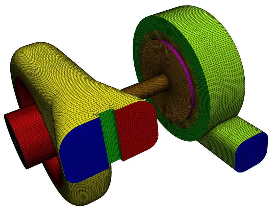
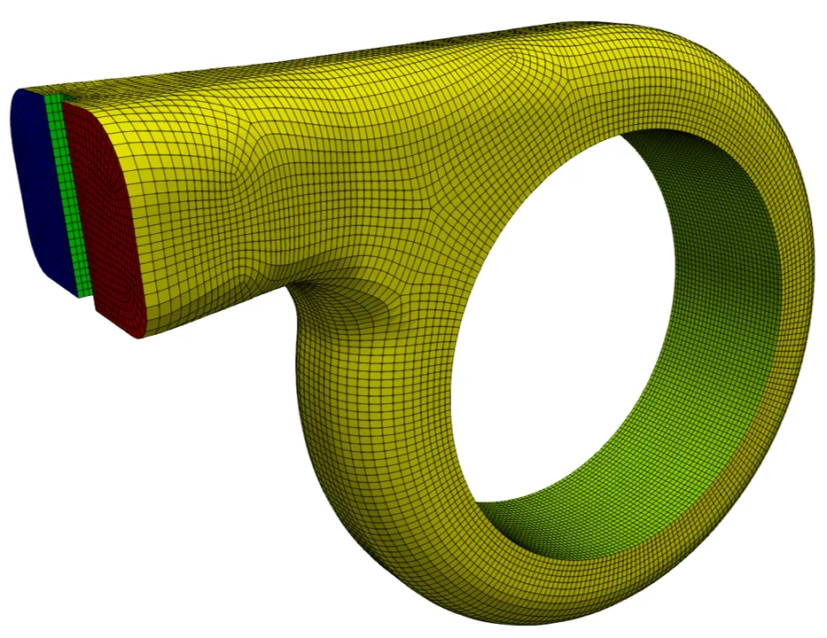
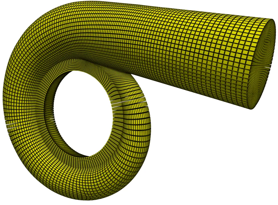
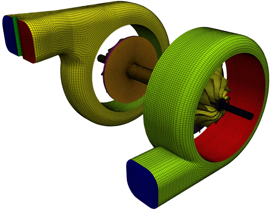
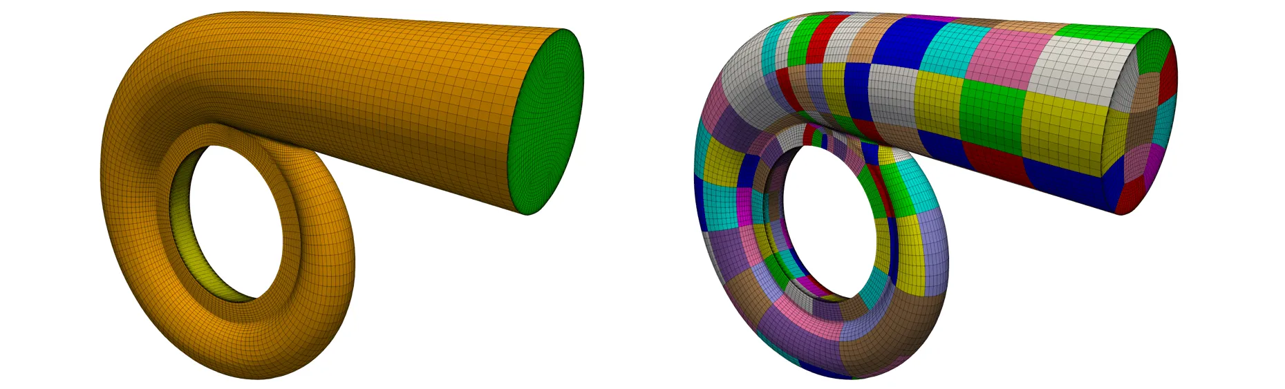
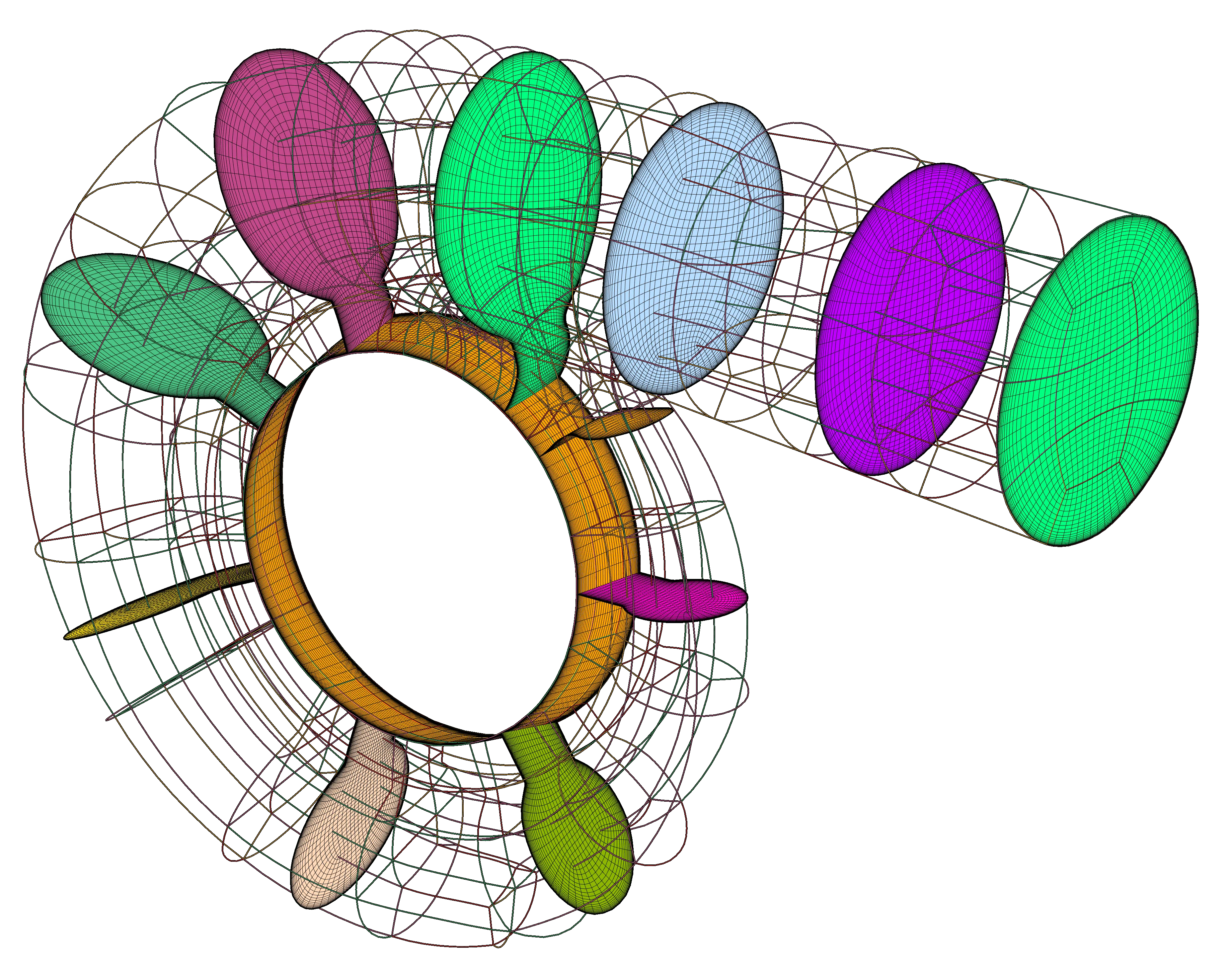
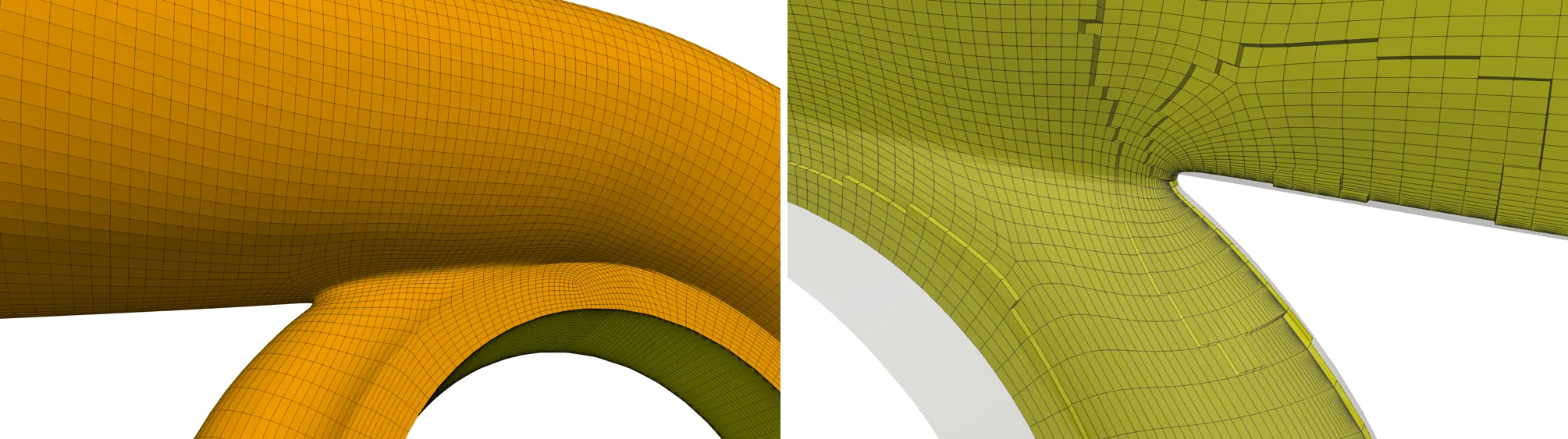
Figure 1: Structured hexahedral volute mesh using GridPro’s automation tool.
Word count: 1660
Discover how GridPro’s automation solution is revolutionizing volute mesh generation for turbochargers, pumps, and compressors. Explore the significance of volutes in engineering, the driving forces behind turbocharger design, and learn how structured meshes drive innovation. Streamline your engineering processes with GridPro’s innovative tool.
Introduction
The shipping industry is propelled by a blend of economic, environmental, and regulatory pressures. Regulations such as the International Maritime Organization’s (IMO) MARPOL Annex VI, limit sulfur oxides (SOx) and nitrogen oxides (NOx) emissions from ships, compelling the industry to adopt cleaner, more efficient technologies.
Also, rising fuel costs and regulations like the Energy Efficiency Design Index (EEDI) mandate improved fuel efficiency in ship designs. Moreover, the quest for operational efficiency and competitive advantage fuels innovation, prompting shipbuilders and operators to seek cutting-edge solutions.
The need for efficient, powerful, and environmentally friendly ship engines is significantly influencing the design and development of turbochargers. Turbochargers, essential for improving engine efficiency and reducing emissions, must evolve to meet these new challenges. They need to be more durable, efficient, and environmentally friendly, pushing engineers to innovate continually.
One key area of improvement in turbocharger performance is the design of the volute. The volute, a spiral casing that guides exhaust gases into the turbine, plays a crucial role in the turbocharger’s efficiency. Optimizing the shape and size of the volute can lead to significant performance gains, including higher pressure ratios, improved airflow, and reduced energy losses. This translates into tangible benefits for ship operators.
CFD plays a pivotal role in the design and development of turbochargers. CFD allows engineers to simulate and analyze fluid flow, heat transfer, and other physical phenomena within the turbocharger, providing insights that are impossible to obtain through traditional testing methods. It enables to identify performance bottlenecks, optimize the shape and size of volutes and other components and explore novel design concepts without extensive physical prototyping. This accelerates the development process and leads to more effective and efficient turbocharger designs.
To further boost the design and development of turbochargers, GridPro is introducing the volute mesh automation. Utilizing advanced meshing algorithms, it creates precise, high-quality meshes for CFD simulations, reducing manual effort significantly. This automation ensures consistent mesh quality, facilitating accurate CFD analyses. Engineers can iterate on volute designs rapidly, optimizing performance and accelerating the overall development of turbochargers and volutes. This ultimately results in better-performing turbochargers tailored to meet the stringent demands of the shipping industry.
Significance of Volutes in Turbochargers
The volute in a turbocharger plays a crucial role by guiding exhaust gas flow from the engine towards the turbine blades, where the exhaust gas’s energy is converted into mechanical energy to drive the compressor. This function is vital, as the volute’s design significantly impacts the efficiency and flow characteristics of the turbine under various operating conditions.
A well-designed volute with an optimal cross-sectional shape is essential for providing uniform flow to the rotor at the desired angle. This uniformity maximizes energy recovery and enhances the efficiency of the turbocharger turbine. The cross-sectional shape of the volute directly influences the direction and magnitude of the flow at the turbine rotor inlet, affecting the overall efficiency of the turbocharger. An optimized volute design can lead to improved cycle-averaged efficiency, especially under the pulsating flow conditions typical of internal combustion engine exhausts. Enhanced efficiency results in better energy recovery from the exhaust gas, thereby increasing the engine’s power density.
Moreover, the cross-sectional shape of the volute impacts secondary flow patterns and the development of vortices within the volute. For instance, a volute designed to produce smaller vortices will exhibit faster response times and superior performance under pulsating conditions compared to one with larger vortices, which have more inertia and respond more slowly.
Different volute designs can lead to varying levels of total pressure loss and flow distortion. A volute with a sharper corner and flatter cross-sectional shape can enhance secondary flow development, resulting in higher pressure losses and more distorted flow at the rotor inlet, which deteriorates the turbine’s performance. Conversely, optimized volute shapes can reduce these losses and improve flow uniformity, contributing to better overall performance.
Additionally, the volute’s design determines its sensitivity to the pulsating nature of the exhaust flow. A well-designed volute can maintain a more stable and predictable flow pattern even under unsteady conditions, which is crucial for maintaining high efficiency and performance in real-world operating conditions of internal combustion engines.
Basically, the volute is a critical component in a turbocharger that significantly affects its performance by influencing flow patterns, efficiency, pressure losses, and sensitivity to pulsating flow conditions. Optimizing the volute design can lead to marked improvements in turbocharger efficiency, power density, and overall engine performance.
Factors Driving the Design and Innovation of Turbochargers
The evolution of turbocharger design is steered by a multitude of factors, each contributing to the relentless pursuit of innovation and efficiency across the automotive, shipping, and aerospace industries.
A primary force behind this evolution is the increasingly stringent emissions standards worldwide. Manufacturers are under pressure to develop turbochargers that enhance engine thermal efficiency and significantly reduce CO2, NOx, and particulate matter emissions. Turbocharging plays a pivotal role in meeting these regulatory requirements by improving combustion efficiency.
Concurrently, the growing emphasis on fuel economy and sustainability is pushing turbocharger designs to focus on enhancing engine efficiency. The goal is to increase power output without a significant rise in fuel consumption.
This is particularly important as the trend towards downsizing engines continues to gain traction. By reducing engine size while maintaining or improving performance, turbochargers enable smaller engines with reduced displacement to produce the same or higher power outputs. This is achieved by increasing the air intake pressure, thereby enhancing volumetric efficiency. When downsizing is combined with downspeeding—operating at lower engine speeds—fuel consumption is further reduced, and vehicle weight is minimized.
Despite these advancements, traditional turbochargers often suffer from slow transient response, which negatively impacts vehicle drivability and acceleration. To address this issue, innovations such as electrically-assisted turbochargers are being developed. These new designs improve response time without causing parasitic losses to the engine, a crucial improvement for maintaining the performance and attractiveness of turbocharged vehicles.
Intense competition in the automotive industry further motivates manufacturers to continuously innovate turbocharger designs, striving to stay ahead in terms of performance, efficiency, and reliability. This competitive drive is closely linked to the need to meet specific market demands and customer expectations. As a result, there is a strong focus on developing turbochargers that offer better drivability, fuel efficiency, reduced turbo-lag, and overall improved vehicle performance.
Technological advancements play a significant role in this ongoing evolution. Progress in materials, manufacturing processes, and computational fluid dynamics (CFD) has enabled the development of more efficient and responsive turbochargers. Innovations in materials and structural design contribute to the longevity and reliability of turbochargers, allowing them to withstand high temperatures and high-stress conditions.
In essence, turbocharger design refinement is a dynamic interplay of regulatory pressures, performance demands, technological innovations, market dynamics, and environmental consciousness, all converging to shape the future of propulsion engines.
Driving Innovation: The Role of Structured Meshes in Volute and Turbocharger Advancements
Structured meshes play a pivotal role in propelling the enhancement of volutes and turbochargers, influencing various factors driving design improvements. Firstly, they elevate the accuracy of simulation results, enabling precise predictions of fluid flow behaviours like pressure distributions and velocity profiles. This insight aids engineers in pinpointing areas for enhancement and refining design parameters.
Secondly, structured meshes deepen the comprehension of flow physics within these components, identifying phenomena like flow separation and vortices. This comprehension inspires innovative design concepts and optimization strategies geared towards boosting performance and efficiency.
Moreover, structured meshes facilitate parametric studies, allowing engineers to systematically optimize geometric parameters while maintaining mesh quality. This exploration of the design space leads to the discovery of optimal configurations aligned with performance objectives.
Additionally, these meshes aid in evaluating aero-thermal performance and mitigating flow instabilities, contributing to more robust and reliable designs. They also support the validation of design concepts by providing accurate predictions for comparison with experimental data, reducing development time and accelerating innovation.
In essence, structured meshes serve as the foundation for accurate simulations, fostering deeper understanding, optimization, and validation processes that collectively drive advancements in volute and turbocharger designs.
Automating Volute Mesh Generation
Traditionally, the process of generating high-quality meshes for volutes has been labour-intensive and time-consuming, requiring manual intervention and expertise in meshing software. However, with the unveiling of GridPro’s latest innovation, this cumbersome process is now a relic of the past.
GridPro has introduced an automation tool designed to effortlessly generate topology and mesh for volute geometries. Through its intuitive workflow and robust meshing algorithms, GridPro streamlines the mesh generation process. The algorithm seamlessly generates topology and meshes on volutes with unparalleled efficiency and precision.
Whether it’s creating structured meshes for volutes with intricate geometries or optimizing mesh density for turbocharger simulations, GridPro empowers engineers to achieve superior results with minimal computational overhead.
Embracing Efficiency and Innovation
GridPro’s automated solution for volute geometries represents more than just a technological advancement; it embodies a paradigm shift in engineering design and simulation. By harnessing the power of automation, engineers can transcend the limitations of manual mesh generation, unlocking new possibilities in product development and optimization.
Gone are the days of laborious meshing processes and tedious iterations. With GridPro’s innovation as their ally, engineers can embrace a future of seamless design, where creativity and efficiency converge to propel projects forward.
Ready to Automate Your Meshing Workflow?
Gridpro Xpress Volute
GridPro’s intelligent structured meshing automation solution reduces manual effort and maximizes accuracy—making it ideal for design optimization in CFD.
Schedule a free demo or contact us to see how GridPro can accelerate your simulation pipeline.
Conclusion
In conclusion, GridPro’s automated solution for volute geometries heralds a new era of efficiency and productivity in engineering design. By streamlining the volute mesh generation process and eliminating manual labour, the tool empowers engineers to focus their expertise and creativity on solving complex challenges and driving innovation forward.
As the demands of modern engineering continue to evolve, GridPro remains at the forefront of technological innovation, delivering solutions that redefine the boundaries of possibility. With GridPro’s automation tool, the journey from concept to realization becomes smoother, faster, and more rewarding than ever before.
Further Reading
- Volutes – Did Nature or Need Inspire Turbo-Machines?
- Automation of Hexahedral Meshing for Scroll Compressors
- Automated Structured Meshing of Fuel Rod Assembly
References
1. Discover GridPro Xpress Volute
2. “An investigation of volute cross-sectional shape on turbocharger turbine under pulsating conditions in internal combustion engine”, Mingyang Yang et al, Energy Conversion and Management 105 (2015) 167–177.
3. “The impact of volute aspect ratio and tilt on the performance of a mixed flow turbine”, Samuel P Lee et al, Proc IMechE Part A: J Power and Energy 2021, Vol. 235(6) 1435–1450.
4. “Unsteady behaviours of a volute in turbocharger turbine under pulsating conditions”, Mingyang Yang et al, J. Glob. Power Propuls. Soc. | 2017, 1: 237–251.
5. “The Effect of Volute Design On The Performance Of A Turbocharger Compressor”, A. Whitfield et al, International Compressor Engineering Conference. Paper 1501.
6. “Important Considerations When Designing a Volute”, an article by Jamin Bitter.
7. “How Turbocharger Design is Changing as Car Firms Chase Efficiency”, an article in the website secotools.com
8. “ Turbochargers for higher engine efficiency”, article by Lucie Maluck.
9. “Downsized, boosted gasoline engines”, Aaron Isenstadt and John German (ICCT) et al, INTERNATIONAL COUNCIL ON CLEAN TRANSPORTATION, 2016.
10. “Variable Geometry Turbocharger Technologies for Exhaust Energy Recovery and Boosting‐A Review”, Adam J. Feneley et al, Renewable and Sustainable Energy Reviews 71 (2017) 959–975.
11. “Multi-objective optimization of turbocharger turbines for low carbon vehicles using meanline and neural network models”, Prakhar Kapoor et al, Energy Conversion and Management: X 15 (2022) 100261.
12. “A Review of Novel Turbocharger Concepts for Enhancements in Energy Efficiency”, A. Kusztelan et al, Int. J. of Thermal & Environmental Engineering Volume 2, No. 2 (2011) 75-82.
13. “Electric Turbocharging for Energy Regeneration and Increased Efficiency at Real Driving Conditions”, Pavlos Dimitriou et al, Appl. Sci. 2017, 7, 350; doi:10.3390/app7040350.