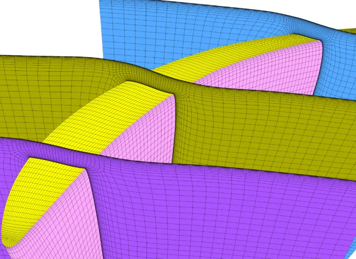
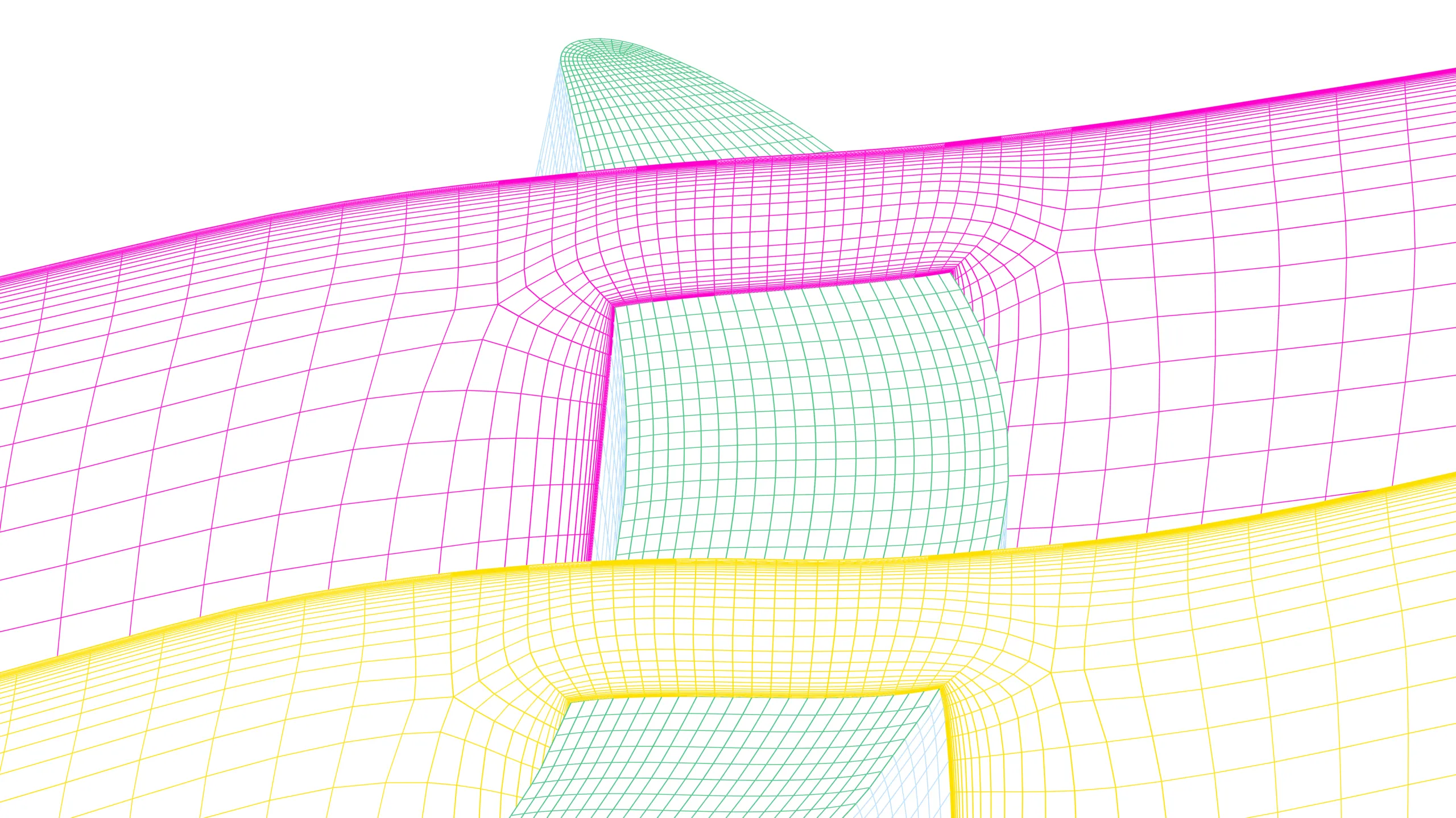
Figure 1: Structured multiblock meshing for tip gaps with multiple slices along the blade chord at the blade tip gap region.
1802 words / 9 mins read
Tip gaps may be small, but their impact on turbomachinery performance is massive. Leakage flows and secondary vortices can quietly erode efficiency if CFD meshing for tip gaps is not done right. This article explains how structured multi-block meshing captures tip leakage flows and secondary flow structures accurately in turbomachinery CFD.
Introduction: Meshing Challenges for Tip Gaps and Leakage Flows in Turbomachinery
In turbomachinery, some of the most serious performance penalties originate in places that are barely visible in the CAD model. A blade tip clearance of just a few millimeters may seem insignificant on screen, but once the rotor is in motion, that narrow gap becomes an active flow path. High-pressure fluid is driven through the clearance, accelerates into a leakage jet, and quickly rolls up into a strong vortex that interacts with the main passage flow.
This interaction is rarely benign. Tip leakage vortices trigger secondary flow structures, increase aerodynamic losses, raise noise levels, and ultimately erode overall efficiency. In compressors and turbines alike, these effects can dominate the performance map, especially at off-design conditions.
Most CFD engineers are well aware of the physics. What often gets underestimated is how much the meshing strategy determines whether these phenomena are captured at all. Tip leakage flows are highly three-dimensional, strongly anisotropic, and extremely sensitive to grid quality. If the mesh fails to resolve the clearance region, the shear layers, and the vortex core correctly, the simulation may converge—but the physics will be wrong.
If the tip leakage vortex is not captured correctly, the downstream solution cannot be relied upon. This may sound blunt, but it reflects the physics of the flow. Errors introduced at the blade tip do not remain localized; they are convected into the passage, distort the wake structure, and propagate through downstream blade rows, compromising the accuracy of the entire simulation.
This article examines the key meshing challenges associated with tip gaps, leakage flows, and secondary flow structures in turbomachinery. It explains why structured multi-block meshes continue to offer the most reliable framework for resolving these flows and how modern tools like GridPro make such high-fidelity meshing practical within real-world industrial workflows.
Understanding Tip Gaps and Leakage Flows in Turbomachinery
Tip gaps exist because blades cannot touch the casing. That clearance creates a pressure difference between the pressure side and suction side of the blade. Fluid naturally wants to move from high pressure to low pressure, so it leaks through the gap.
As the leakage jet exits, it rolls up into what is known as the tip leakage vortex (TLV). This vortex is not small or weak. Experiments and simulations show that it can persist far downstream and interact with wakes, boundary layers, and passage vortices, creating complex three-dimensional secondary flow structures.
Researchers consistently report that tip leakage can account for 20–40% of total aerodynamic loss in turbines, depending on gap size and loading.
This is why tip gaps are not a “detail problem.” They are a core flow physics problem. And core physics demand the right mesh.
Why Tip Leakage Flows Are Difficult to Capture in CFD Meshing
The difficulty with tip leakage flows goes far beyond the fact that the clearance itself is small. The real challenge lies in the number of complex flow mechanisms that occur simultaneously within a very confined region.
In and around the tip gap, the flow is dominated by extremely strong velocity gradients and very thin boundary layers forming on both the blade tip and the casing. High-pressure fluid accelerates through the clearance, rolls up rapidly into a leakage vortex, and begins interacting almost immediately with the main passage flow. In high-fidelity simulations, this process can become unsteady, with vortex stretching, breakdown, and intermittent interaction with the blade wake.
This combination makes the tip region one of the most demanding areas to mesh in turbomachinery CFD.
Unstructured meshes can fill the geometry with ease, but they often struggle to align cells with the dominant flow direction in the clearance and vortex core. The consequence is increased numerical diffusion, smeared vortex structures, and leakage jets that appear weaker and more diffuse than they should. This can occur even at very high cell counts.
The final result may look smooth and well-behaved, but smooth solutions are not necessarily accurate. In tip leakage simulations, visual cleanliness is a poor substitute for physically correct flow structures.
Role of Mesh Quality in Capturing Secondary Flow Structures
In turbomachinery, so-called ‘secondary’ flows are anything but secondary in their impact. Passage vortices, horseshoe vortices, corner separations, and the interaction between tip leakage vortices and endwall flows are often the dominant sources of aerodynamic loss in axial turbines, compressors, and fans. If these structures are not captured accurately, overall performance predictions quickly lose credibility.
Numerous studies have shown that the prediction of secondary flows is highly sensitive to mesh quality, particularly near endwalls and blade tips where flow turning, separation, and vortex formation are strongest. Mesh resolution alone is not sufficient. Cell alignment with blade surfaces and local flow paths plays a decisive role in controlling numerical diffusion and preserving vortex strength.
Structured meshes, when properly designed, offer a clear advantage in this context. By aligning grid lines with the blade geometry and expected flow directions, they resolve secondary flow structures more cleanly and with fewer cells than unstructured alternatives. The result is lower numerical error, sharper vortical features, and more reliable loss predictions.
For this reason, turbomachinery CFD best-practice guidelines continue to favor structured or hex-dominant meshing approaches when high accuracy is required. The flow physics may be inherently three-dimensional, but capturing it faithfully still depends on a disciplined, well-aligned grid.
Structured Multi-Block Meshing for Tip Gaps and Leakage Flows
Structured meshes may not be new, but in turbomachinery CFD they remain exceptionally difficult to outperform—especially when tip gaps and leakage flows are involved. The reason is straightforward: these flows are highly directional, strongly influenced by the blade geometry, and extremely sensitive to numerical dissipation.
A well-designed structured multi-block mesh naturally aligns grid lines with the blade surfaces and dominant flow paths. This alignment allows boundary layers to be resolved cleanly, shear layers to remain sharp, and vortical structures to retain their strength as they convect downstream. In regions such as tip gaps, where velocity gradients are severe and vortex roll-up happens over very short length scales, this alignment becomes critical.
Compared to unstructured grids, structured meshes consistently deliver higher accuracy per cell. By reducing numerical diffusion in vortical and high-gradient regions, they capture leakage jets and tip vortices more faithfully without relying on excessive cell counts. Numerous comparative studies have shown that structured approaches achieve the same—or better—solution fidelity with significantly fewer cells, particularly in challenging areas like blade tips and endwalls.
This advantage becomes even more pronounced for LES and other scale-resolving simulations. In these cases, preserving vortex strength, breakdown behavior, and unsteady interactions is essential, and any artificial dissipation introduced by the mesh directly degrades the solution.
Ultimately, structured multi-block meshes do more than produce visually clean grids. They preserve the underlying physics of tip leakage and secondary flows, which is exactly what high-fidelity turbomachinery simulations demand.
Why Structured Multi-Block Meshes Are Preferred in Turbomachinery CFD
High-quality turbomachinery meshes tend to share a small set of proven design principles. At the core is multi-block decomposition, which allows the blade tip region to be isolated from the rest of the domain. By treating the tip gap as its own topological entity, engineers gain precise control over wall-normal spacing, gap resolution, and grid stretching—without forcing unnecessary refinement elsewhere.
This localized control makes it possible to focus resolution exactly where it matters. Leakage jets and tip vortices can be refined aggressively in their formation and roll-up regions, while the remainder of the passage retains a coarser, well-aligned mesh. The result is a simulation that remains computationally efficient yet still captures the flow physics that drive loss and performance.
In particularly complex geometries, limited hybrid strategies are sometimes unavoidable. Even then, the structured mesh typically dominates the regions that matter most from a physics standpoint. Published studies consistently show that when unstructured elements encroach into the tip clearance, the prediction of leakage flow strength and vortex structure deteriorates rapidly.
For turbomachinery CFD, this is not a matter of preference but of practicality. Structured multi-block meshes provide the control, alignment, and numerical discipline required to resolve tip leakage and secondary flows with confidence—something alternative approaches still struggle to match.
How GridPro Enables Accurate Meshing of Tip Gaps and Leakage Flows
This is where GridPro integrates naturally into high-fidelity turbomachinery CFD workflows. The software is built around structured multi-block meshing, an approach that aligns closely with the geometric and physical demands of tip gaps, leakage jets, and secondary flow structures. By using a topology-driven framework, GridPro allows blocks to be placed deliberately along blade surfaces, endwalls, and clearance regions, ensuring that the mesh follows both the geometry and the expected flow paths with high precision.
For turbines and other rotating machines, this approach translates directly into practical advantages. Mesh density across blade tips can be controlled explicitly, allowing leakage jets and vortex cores to be resolved without over-refining the entire domain. Boundary layers on the blade and casing are captured cleanly and consistently, which is essential for predicting losses and wall shear accurately. Just as importantly, the block topology remains stable across design variants, making GridPro well suited for parametric studies and design optimization.
The resulting grids are efficient and robust, supporting a wide range of turbulence modeling strategies, from steady RANS to URANS and scale-resolving LES. Instead of struggling to accommodate complex geometry, the meshing process reinforces the underlying physics. In regions where tip leakage and secondary flows originate and evolve, the mesh becomes an enabler rather than a limitation—exactly what is required for reliable turbomachinery CFD simulations.
Conclusion: Why Structured Meshing Is Key for Tip Leakage Prediction
Tip gaps, leakage flows, and secondary flow structures are not peripheral effects in turbomachinery—they sit at the heart of aerodynamic performance, efficiency, and long-term reliability. In many machines, these flows dominate the loss budget and strongly influence noise, heat transfer, and downstream blade loading.
Accurately capturing this behavior requires more than simply adding cells. The meshing strategy must respect the dominant flow directions, resolve thin boundary layers, and preserve vortex formation and evolution without excessive numerical dissipation. When these requirements are not met, even well-converged solutions can deliver misleading results.
Decades of published research and practical industry experience converge on a clear outcome: structured multi-block meshes remain the most reliable way to resolve tip leakage and secondary flows in turbomachinery CFD. When the grid is aligned with the physics, the simulation provides a far more trustworthy view of the flow phenomena that ultimately determine machine performance.
Further Reading
- The Art and Science of Meshing Turbine Blades
- Innovative Turbine Blade Tips to Reduce Tip Leakage Flow
- Efficient Meshing of Turbine Blade Cooling Holes !
- Automated Hexahedral Meshing with GridPro: Structured Meshes for Parametric Geometry Variants
References
1. Three-dimensional losses and correlation in turbomachinery.
2. “Numerical Analysis of the Effects of Different Rotor Tip Gaps in a Radial Turbine Operating at High Pressure Ratios Reaching Choked Flow”, José Galindo et al, Energies, 2022, 15(24), 9449.
3. Best practice guidelines for turbomachinery CFD
4. “Multiblock Structured Mesh Generation for Turbomachinery Flows”, Zaib Ali et al, Proceedings of the 22nd International Meshing Roundtable, January 2014.
5. “Tip-leakage-flow excited unsteadiness and associated control”, Yabin Liu et al, arXiv:2405.09347, 15 May 2024.
6. “User-intervened structured meshing methods and applications for complex flow fields based on multiblock partitioning”, Wen-Hao Cai et al, Journal of Computational Design and Engineering, Volume 8, Issue 1, February 2021, Pages 225–238.
7. “A mesh adaptation strategy for complex wall-modeled turbomachinery LES”, Nicolas Odier et al, Computers & Fluids, Volume 214, 15 January 2021, 104766.