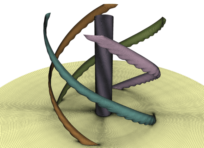
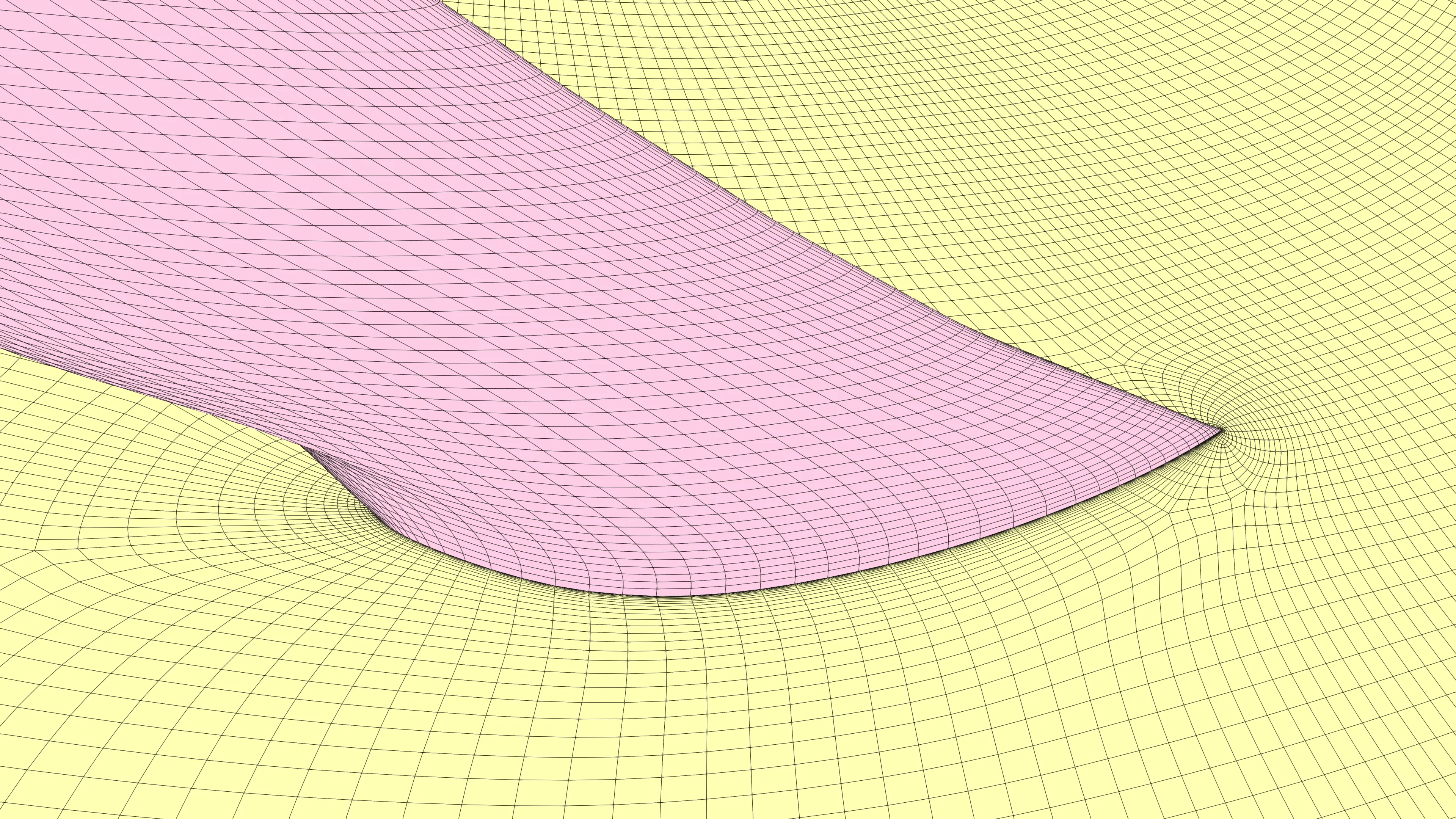
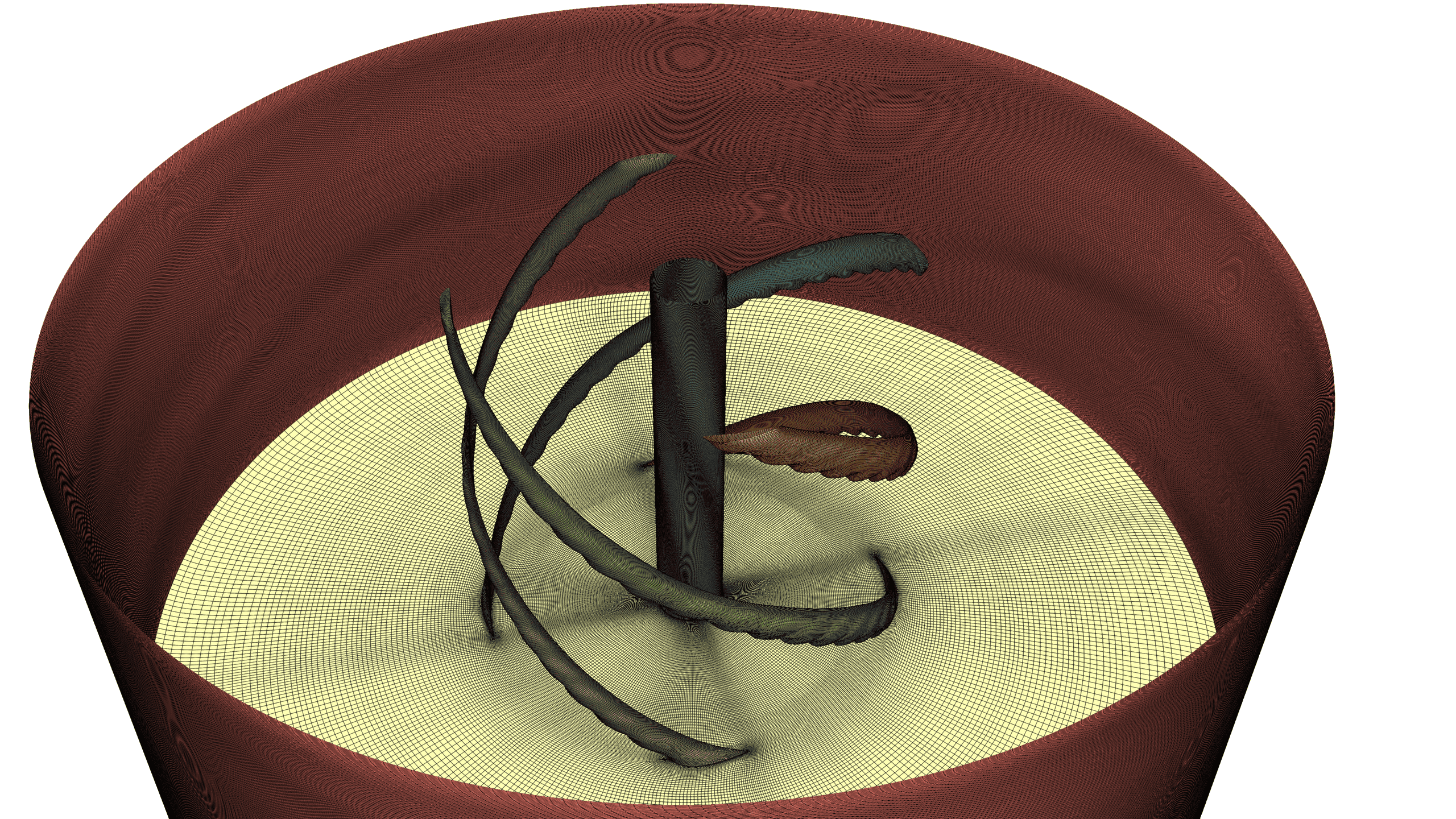
Figure 1: Structured meshing of serrated and wavy blade edges used for wind turbine noise reduction.
1933 words / 10 min read
Wind turbine noise isn’t just an annoyance — it’s a design challenge engineers can actually solve. Serrated and wavy blade edges are transforming how we control wind turbine aeroacoustics. But predicting their impact starts with one thing: the mesh. Here’s how advanced CFD meshing unlocks quieter, more efficient wind turbines.
Introduction
If you’ve ever stood beneath a wind turbine on a windy afternoon, you know the sound isn’t just background ambience—it’s a deep, rhythmic whoosh that feels woven into the landscape. What many don’t realise is that this noise comes from tiny aerodynamic interactions happening along the blade edges, especially where the turbulent boundary layer meets the trailing edge. Over the last decade, engineers and researchers have found a clever way to achieve meaningful wind turbine noise reduction using serrated trailing edges and wavy or tubercled leading edges.
These bio-inspired geometries are reshaping wind-turbine aeroacoustics. By disrupting how turbulent eddies strike the blade edges, serrations and wavy patterns help scatter sound more softly, reducing the intensity and coherence of noise radiation. But while the idea sounds simple on paper, accurately predicting their noise-reduction behaviour inside CFD is anything but straightforward.
Here’s the truth most newcomers underestimate: the mesh is everything. If your CFD mesh can’t capture the sharp serration tips, the peaks and troughs of a wavy edge, or the delicate vortices rolling off these features, your simulation may confidently predict a quieter blade that never materialises in reality. High-fidelity aeroacoustic prediction depends on resolving small-scale turbulence—and that means building a mesh that honours every millimetre of geometric detail.
In this blog, we break down why serrated and wavy edges work, the CFD approaches used to model them, the meshing challenges engineers face, and why structured multiblock meshing with tools like GridPro offers a far more reliable path to accurate, trusted results.
By the end you’ll have a stronger understanding of how to mesh blade variants with serrated or wavy features for accurate wind turbine aeroacoustic predictions — and why that matters for quieter wind turbines.
Why Serrated and Wavy Edges Reduce Wind Turbine Noise
To understand why serrated and wavy blade edges help reduce wind-turbine noise, picture what happens on a smooth trailing edge. As the turbulent boundary layer approaches the edge, the eddies arrive in a relatively coherent band across the blade span. When these eddies meet a straight, sharp trailing edge, they scatter efficiently and radiate sound—forming the familiar broadband “whoosh” we hear around wind turbines.
Serrated trailing edges disrupt this coherence in a very intentional way. Their saw-tooth geometry causes turbulent eddies to hit the edge at different spanwise positions and at staggered times. Instead of one strong, unified scattering event, the noise source becomes fragmented and weakened.
Wind-tunnel experiments consistently show several decibels of broadband wind turbine noise reduction using these serrated patterns.
Wavy or tubercled leading edges work further upstream but rely on similar physics. Their undulating surfaces create spanwise variations in pressure and flow structure, delaying separation and suppressing large coherent vortices—key contributors to noise generation. Multiple CFD and experimental studies report measurable reductions in wake turbulence and acoustic emissions, with sensitivity to geometric parameters such as amplitude and wavelength.
Because these benefits arise from small-scale, geometry-driven flow physics, accurate noise prediction depends directly on a mesh capable of resolving every serration tip and wave contour.
How CFD Models Serrated, Wavy and Tubercled Blade Edges
Capturing the aeroacoustic behaviour of serrated, wavy, and tubercled blade edges requires more than a standard aerodynamic simulation. These geometries generate small-scale vortices, fluctuating pressure fields, and unsteady boundary-layer structures that directly influence noise. To resolve these details, engineers often rely on high-fidelity CFD approaches such as URANS, DES, LES, or hybrid methods. For far-field acoustic prediction, the Ffowcs Williams–Hawkings (FWH) analogy remains the most widely used acoustic model.
Why such fidelity? Because the serration tips and wavy contours produce intricate, time-dependent vortical structures. If the mesh or solver cannot resolve these features, the acoustic sources are inevitably under-predicted.
Studies repeatedly highlight that the wake region just downstream of serration tips must be finely resolved to capture the breakdown of coherent turbulence. Similarly, research shows that serration amplitude and wavelength strongly influence acoustic behaviour — but only when the mesh has sufficient spanwise and streamwise fidelity.
CFD models must also capture the spanwise flow variations induced by tubercled or wavy leading edges. These undulations shift local pressure gradients, delay separation, and suppress large vortical structures, all of which feed into broadband noise sources.
Ultimately, accurate aeroacoustic prediction hinges on a mesh that respects geometric detail, preserves flow gradients, and supplies the resolution demanded by turbulence-driven sound generation.Having covered how CFD works for these features, let’s dig into the meshing challenges.
CFD Meshing Challenges and Best Practices for Serrated, Wavy & Tubercled Blades
Why These Geometries are Hard to Mesh
Serration tips, tubercle peaks, wavy leading-edges: they all introduce rapid curvature changes, small radii, and spanwise undulations. That means higher geometric complexity compared with a smooth blade. To capture the physics, the mesh must place small cells around the serration features, preserve boundary-layer resolution (y+ targets), and ensure good cell quality despite the undulating surface.
Common Meshing Challenges
- Small feature size & high curvature. The serration tip radius and the undulation amplitude are small compared to the main chord length. That forces local cell size reduction.
- Boundary-layer resolution variation. As the surface undulates, the growth of the boundary layer and the effective surface normal direction vary; maintaining consistent y+ across peaks and troughs is tricky.
- Spanwise resolution across feature wavelength. If the serration or tubercle wavelength isn’t adequately resolved in the spanwise direction, the mesh suppresses the very flow variations that enable effective wind turbine noise reduction.
- Transitions in mesh cell size and block topology. Going from fine mesh around the serration tips to the coarser far-field mesh can create poor quality elements unless transitions are managed.
- CAD fidelity vs mesh ease. Over-smoothing the serrations in CAD to make meshing easier may remove the very physics you intend to capture. So the mesh generation must respect the real geometry.
In short, the geometry itself sets a high bar—and only a well-designed mesh can clear it.
What Research Studies Reveal About Meshing These Blade Geometries
Across wind-turbine aeroacoustics literature, one theme appears repeatedly: serrated, wavy, and tubercled blade edges demand significantly higher mesh fidelity than smooth blades. Multiple studies report that accurate noise prediction hinges on resolving the small-scale vortices forming near serration tips and wavy contours. Mesh-convergence analyses consistently show that only fine, body-fitted structured grids maintain the coherence and turbulence characteristics needed for reliable acoustic trends. Leading-edge tubercle research further highlights that blocking topology directly affects predicted separation behaviour, making mesh design as important as solver choice. As noted in the Hand Book of Grid Generation, mesh quality remains one of the strongest determinants of aeroacoustic accuracy.
Recommended Meshing Strategies for Accurate Wind Turbine Noise Reduction Prediction
- Local multiblock refinement around serrations/tubercles. Create dedicated small blocks that conform to the serration geometry, allowing cell size control and orthogonal cells at the feature.
- Curvilinear/ body-fitted hexahedral or prismatic layers in boundary layer region. These ensure wall-normal layering meets y+ targets, even on undulating surfaces.
- Spanwise cell count matched to serration/tubercle wavelength. Design the mesh so that each serration or wave feature is represented by sufficient spanwise nodes.
- Smooth block transitions and growth rates. Avoid abrupt size changes. Use transition blocks and nesting/coarsening strategies away from feature regions.
- Mesh-sensitivity testing early. Instead of relying on a single “fine enough” mesh, run coarse–medium–fine meshes focused on acoustic and aerodynamic metrics to ensure convergence.
–Hybrid meshing/practical compromise. If LES everywhere isn’t feasible, use RANS near-wall + DES/WMLES in the wake, but still ensure the serration-tip region is refined.
Practical Pitfalls and “Gotchas”
- Over-defeaturing the serration geometry kills the noise-reduction physics.
- Inconsistent y+ across serration crest/trough: walls see different layer thickness but solver expects uniform.
- Forgetting to refine spanwise: serration effect may vanish if you have only one cell per wavelength.
- Assuming unstructured tetra meshes will “just work”: they may simplify meshing, but for acoustic prediction they often underperform.
- Not accounting for full-scale manufacturing or attachment issues (which may show up as cracks/looseness and change blade behaviour in real life).
Here’s a Quick Checklist:
- Clean CAD but preserve serration/tubercle profile.
- Build multiblock patches aligned to serration/wave geometry.
- Stack body-fitted layers with controlled stretching, meet y+ ~1-5 (for LES) or as required.
- Ensure spanwise resolution: at least N nodes per wavelength.
- Use block transitions so skewness/aspect ratio remain acceptable.
- Do mesh-independence study on both aerodynamic forces (Cl, Cd) and acoustic metrics (SPL, spectra).
- Document mesh topology and cell counts — this transparency increases trust in results.
All of these points naturally lead into why structured multiblock meshes — when done right — make a big difference, and how tools like GridPro support them.
Why Structured Multiblock Meshes Help (and Why GridPro Excels)
Advantages of Structured Multiblock for Serrated/Wavy Blade Edges
Structured multiblock meshes align cells with the flow, preserve orthogonality and have predictable convergence behaviour. For serrated or wavy blade edges, you gain:
- Better orthogonality and cell quality around high-curvature features.
- More control of cell size and layering: the near-wall and wake regions benefit.
- Easier to perform systematic mesh refinement studies because block topologies are consistent.
- Lower numerical dissipation and better wake/tip vortex resolution → more accurate wind turbine noise reduction predictions.
How GridPro Tools Make Meshing Easier for Wind Turbine Noise Reduction Simulations
Here are how specific features map to our problem:
- Auto-Topology Templates (in GridPro): For blade variants with serrated or wavy edges, you can define repeating block patterns tailored to each serration or wave. That helps control spanwise cell count, ensure consistency for design variants, and reduce manual effort.
- Local Adaptive Refinement (Enrichment Tool): Allows fine mesh just at serration tips or tubercle peaks without exploding the global cell count.
- Boundary-Layer Control Tools: Maintain high-quality orthogonality and layering even when geometry undulates.
- Xpress Wind Turbine for Full 3D Blade Meshing: Xpress Wind Turbine automates full 3D blade meshing, with smooth transitions from root to tip.
By using structured multiblock workflows and the right meshing toolchain, you turn a “hard to mesh” blade geometry into a trusted simulation setup.
Conclusion
Serrated, wavy, and tubercled blade edges are powerful design features for achieving reliable wind turbine noise reduction, but unlocking their full potential in simulation depends heavily on mesh quality. These geometries introduce sharp curvature, small feature sizes, and complex spanwise variations—all of which demand high-fidelity, structured meshing to accurately capture turbulence and acoustic sources. A standard or loosely refined mesh simply cannot resolve the fine-scale vortices responsible for noise generation and reduction.
Structured multiblock meshes offer the precision and control required to model these features with confidence. Their superior cell alignment, consistent topology, and low numerical dissipation make them an excellent foundation for aeroacoustic CFD. When combined with GridPro’s topology templates, refinement tools, and blade-specific automation, engineers can efficiently generate meshes that meet the resolution needs of URANS, DES, and LES-based noise prediction.
Ultimately, quieter wind turbines begin with the mesh. By prioritizing mesh fidelity—especially around serrated and wavy edges—engineers bridge the gap between “quiet in simulation” and quiet in real-world performance.
Interested in Using GridPro for Your Wind Turbine Meshing Projects?
GridPro’s advanced multi-block structured meshing tools deliver the precision, efficiency, and scalability needed for aerodynamic simulations of turbine blades and rotors.
Click Here to Learn More or Request a Demo.
Further Reading
- The Best Way to Mesh Vortex Generators (VGs) for Accurate Wind Turbine CFD
- How CFD Meshes Are Built for Modern Wind Turbine Blades: Why Structure Still Wins
- Capturing Tip Vortices: LES Meshing Strategies Using Structured Multi Block Grids
- Nesting Your Way to Mesh Multi-Scale CFD Simulation!
Reference
1. “Leading-edge serrations for performance improvement on a vertical-axis wind turbine at low tip-speed-ratios”, Zhenyu Wanga et al, Applied Energy 208 (2017) 1184–1197.
2. “Leading edge serrations for the reduction of aerofoil selfnoise at low angle of attack, pre-stall and post-stall conditions”, Giovanni Lacagnina et al, International Journal of Aeroacoustics, 2021, Vol. 20(1–2) 130–156.
3. “Numerical study of owls’ leading-edge serrations”, Asif Shahriar Nafi et al, Physics of Fluids 35, 121913 (2023).
4. “The Tubercles on Humpback Whales‘ Flippers: Application of Bio-Inspired Technology”, Frank E Fish et al, Integrative and Comparative Biology, volume 51, number 1, pp. 203–213.
5. “Airfoil noise reduction by serrations and/or tubercles and model-to-full scale noise transposition”, Michel Roger et al, PIBE Project report, Work Package 3, June 1, 2024.
6. “Reduction of wind turbine noise using optimized trailing edge serrations.”, Oerlemans, S., Fisher, M., Maeder, T., & Kotsiyannis, K. (2009).
7. “Bioinspired Trailing Edge Serrations for Vertical Axis Wind Turbine Blades in Urban Environments: Performance Effects”, Luis Santamaría et al, Journal of Bionic Engineering (2025) 22:822–837.
8. “Reduction of wind turbine noise using optimized airfoils and trailing-edge serrations”, S. Oerlemans et al, NLR-TP-2009-401.