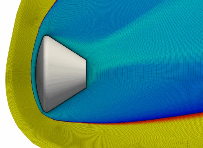
Figure 1: Block Adapted Shock Fitted Structured Grid for Hypersonic Simulations for Orion Reentry Capsule Configuration.
1483 words / 7 minutes read
Discover the advancements in flow feature-aligned structured grid generation for hypersonic simulations with strong shocks. This article explores the innovative shock-fitting feature in GridPro, which aligns mesh blocks with shock contours to improve accuracy and reduce computational costs. Learn how this new technique outperforms traditional methods by simplifying grid alignment and enhancing shock capture, making it ideal for complex geometries with multiple shocks.
Introduction
Computational fluid dynamics is critically essential and highly recommended for predicting the aerothermal environment of reentry vehicles experiencing hypersonic flow. In these regimes, shock waves are a dominant flow phenomenon. It is needless to say capturing these shock waves to the finest level possible is critically essential for accurately predicting the hypersonic flow field. Traditionally, two distinct approaches, known as shock fitting and shock capturing, have been widely used to handle such discontinuities.
Shock Capturing involves implicit handling of shocks through numerical schemes that can deal with discontinuities without explicitly locating them. They employ artificial viscosity or flux limiters to stabilize the solution and prevent non-physical oscillations. However, they may produce smeared shock profiles and require fine grids to achieve higher accuracy, potentially increasing computational costs.
Shock Fitting, on the other hand, explicitly tracks the position of shock waves within the CFD domain. It treats the shock as a moving boundary within the domain, solving additional equations to update its position and speed. This approach provides a sharp and accurate representation of shocks without the smearing effects seen in shock capturing. However, it is more complex to implement, requiring additional equations for shock dynamics and frequent grid adjustments to accommodate moving shocks.
To sum up, shock capturing is robust, versatile and easier to apply to a wide range of problems, albeit with potential accuracy trade-offs. while on the other hand, shock fitting offers superior accuracy for specific applications but at the cost of increased complexity and implementation effort.
To tackle the challenge of accurately representing shock features, engineers at GridPro have developed a new feature, which enables shock-fitted structured grid generation by aligning grid blocks with the shock contour. This article provides an in-depth discussion of this novel method.
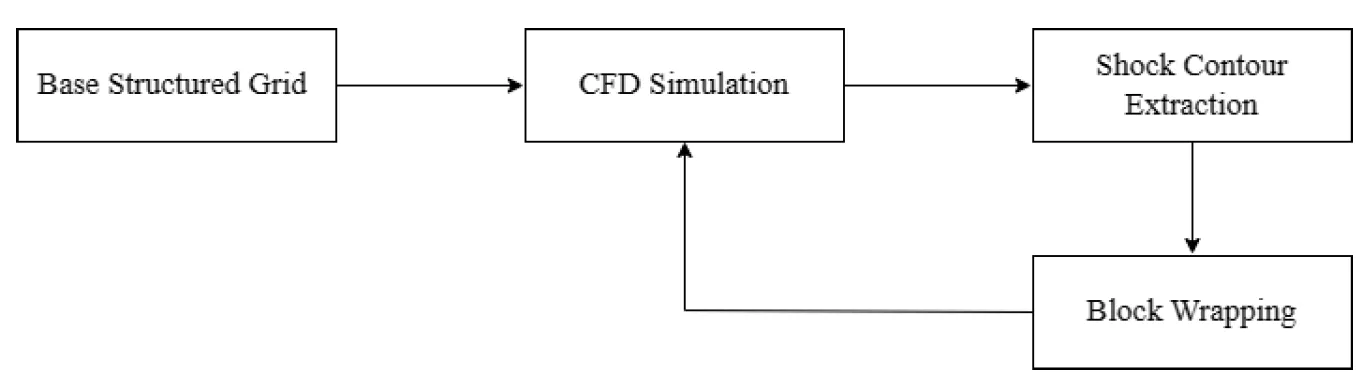
Workflow of the Block-Adapted Shock-Fitting Approach
The computational fluid dynamics workflow begins with the creation of a base structured multi-block mesh for the desired geometry and conducting an initial CFD simulation using this mesh. Following this, post-processing is carried out to extract an iso-contour Mach sheet that passes through the shock.
This Mach iso-contour surface serves as a reference to realign the mesh blocks. By adjusting the topology to align the blocks with the shock, a new mesh is generated with cells more effectively positioned to capture the thin, three-dimensional shock. This updated grid is then used for a second simulation, and the process is repeated until the user achieves the desired level of accuracy in the results.
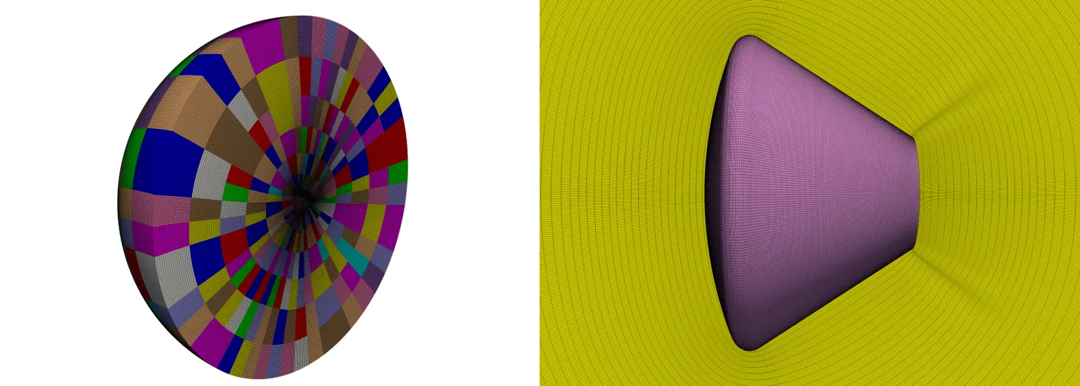
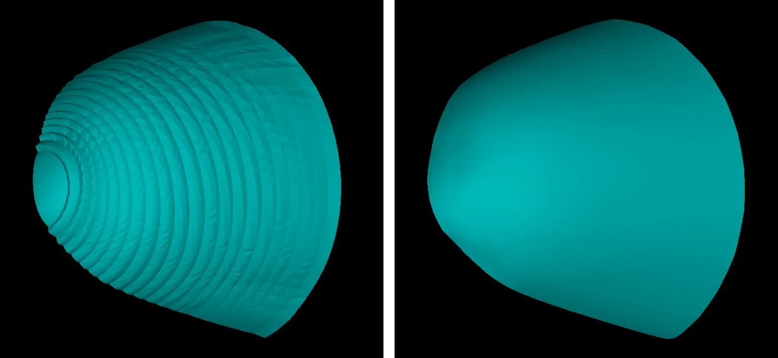
Generating the Baseline Mesh
To commence the simulation, an initial structured grid must be created. The baseline mesh adopts an analytical sphere as its outer domain, with no specialized adjustments made to accommodate shock features. This streamlined approach allows for swift setup of the initial grid, requiring minimal effort and time investment. Furthermore, maintaining symmetry along the X-Y plane aids in reducing grid points, thereby enhancing simulation efficiency.
Initial Solution Generation
Following the structured grid generation, the flow simulation is conducted using MISTRAL, a Navier-Stokes solver tailored for reacting flows.
Initially, the solution is computed on an Euler grid, without implementing specialized boundary layer clustering for the capsule wall.
This simplification is deliberate, aimed at minimizing computational time, as the primary focus of the initial iteration is the extraction of the shock surface.
Shock Detection and Mach Iso-Contour Extraction
The process of detecting and extracting shocks commences with the post-processing of the MISTRAL solution to derive the Mach distribution in the flow domain. The location of the bow shock is determined by selecting a percentage of the freestream Mach number, typically ranging between 90% to 95%. Subsequently, a Mach iso-contour sheet is extracted from the flow solution utilizing the Paraview visualization package. Following the extraction, the Mach sheet is saved as an STL file and imported into GridPro for further processing.
Shock Contour Smoothing
Given the coarse resolution of the bow shock on the initial grid, the Mach iso-surface may display roughness. To address this, a smoothing process becomes imperative. Utilizing GridPro’s built-in subdivision scheme, the extracted Mach contour is smoothed and enhanced to make it more suitable for subsequent stages of the shock-capturing procedure.
The Block-Adapted Shock-Fitting Process
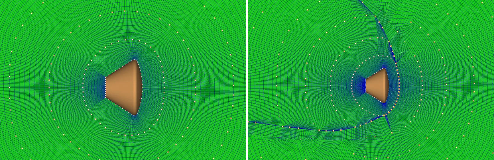
With the shock contour sheet in hand, we’re ready to delve into the actual shock-capturing process. Firstly, the tool automatically pinpoints the block faces closest to the extracted shock contour sheet. Next, those faces proximate to the shock undergo splitting and a buffer layer of the block is created around the shock. Notably, this splitting operation maintains the integrity of the block structure, relieving the user from the burden of resolving any ensuing issues.
Following this, blocks lying beyond the buffer layer are automatically deleted (as shown in Figure 7a). Next, a new outer domain surface, encapsulating the capsule is generated by scaling up the shock contour sheet by a small percentage.
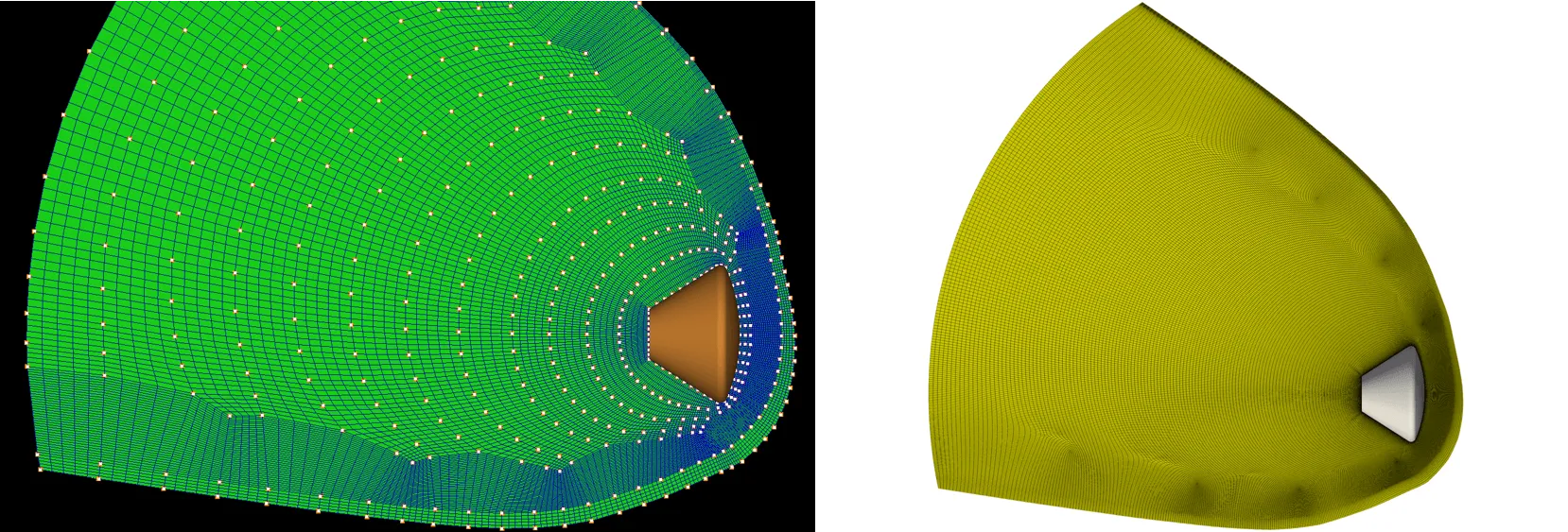
Consequently, the outer faces of the buffer layer blocks serve as the boundary faces of this new outer envelope, establishing a zone characterized by shock-aligned grid lines. A detailed view of the mesh obtained after the initial shock-fitting iteration is presented in Figure 7b.
It’s important to note that the decision to split the topology hinges on the specifics of each case. In scenarios where there’s no need to reduce the computational domain’s size, this step may be bypassed. However, in instances like the one described here, where pinpointing the shock’s location and the primary flow physics region is challenging before simulation, employing this process can significantly slash the computational domain by over half. Such reduction translates into substantial savings in computational time and resources.
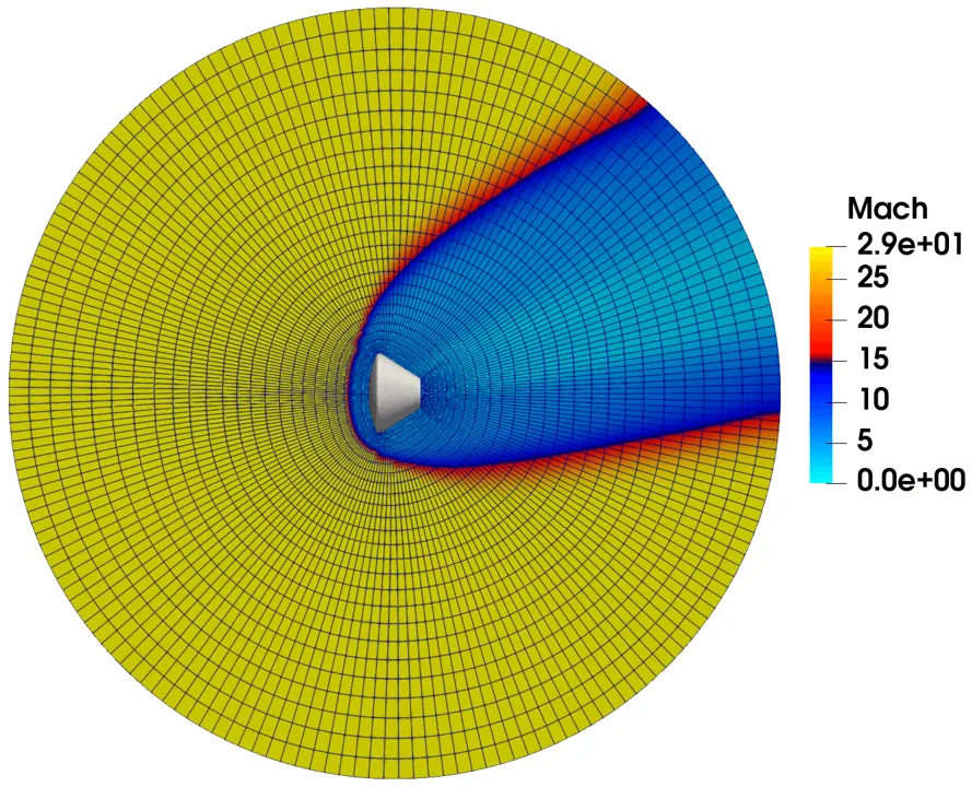
Shock-Fitted CFD Solution
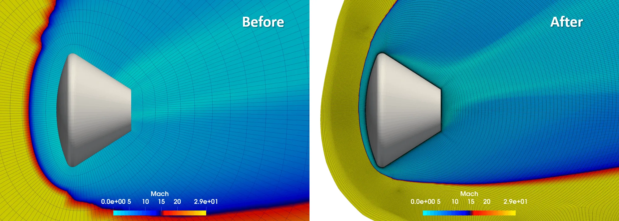
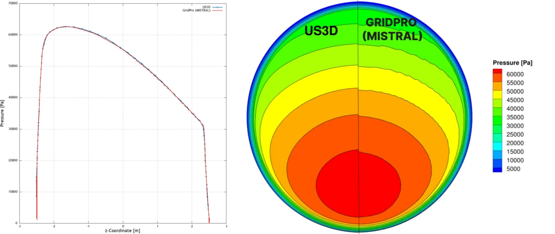
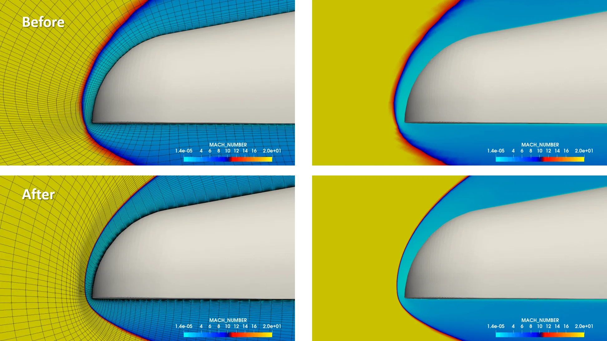
The Mach contour image in Figure 8 clearly demonstrates that the shock is significantly crisper and closer to the body. The cells are noticeably better aligned with both the general flow direction and the shock’s location. Remarkably, just one shock-fitting iteration was sufficient to achieve a good solution, highlighting the efficiency and effectiveness of the block-adapted shock alignment method.
The computed results are compared to data from Reference, which utilizes the US3D code. Figure 9 compares surface pressure variation along the symmetry line (in the z direction) of the capsule. The maximum pressure error is less than 1%, which is well within acceptable standards, validating the quality of the obtained solution.
Case 2: Space Launch System
The next test case considered to validate the tool was the leading nose region of the Space Launch System. Two structured grids were generated- a baseline grid (0.7 million) and a shock-fitted grid (0.762 million) and CFD computations were done at Mach 5. Figure 10 shows the grids and the improvement in the flow field with the block-adapted shock alignment method.

Case 3: Hypersonic Simulations for a Blunt Body with Fin
The third test case involves hypersonic simulations for a blunt body configuration at Mach 20. Here also 2 grids – Baseline (5.92 million) and shock-fitted grids (5.61 million) were employed. Figure 11 below shows the crisp representation of the bow shock with block-adapted shock-fitted grids.
Advantages of the Block-Adapted Shock-Fitting Approach for Hypersonic Simulations
The block-adapted shock alignment approach is straightforward to implement, requiring fewer re-meshing and CFD simulation iterations compared to other shock-fitting procedures or adaptive shock-capturing methods. Additionally, it only increases the cell count of the base grid by a smaller amount.
This method can be seamlessly integrated into the existing GridPro-CFD solver-post-processor loop without any modifications. The base-structured hexahedral meshes, with their inherently low dissipation properties, enhance shock capture accuracy. By using the shock surface to identify shock-interfering blocks and refining these blocks through wrapping, the resulting grid is sufficiently dense and aligned with the shock contour to capture it accurately. Typically, executing this loop for one or two iterations is sufficient.
A key advantage of this approach is the minimal increase in cell count and the presence of one-to-one connected cells. Due to the limited number of iterative loops and uni-directional cell refinement, the increase in cell count remains marginal. Importantly, any computational fluid dynamics solver compatible with hexahedral meshes can utilize the shock-fitted grids, as one-to-one cell connectivity with neighbouring cells is consistently maintained.
Conclusion
A workflow for shock-fitting grid generation has been developed and rigorously tested, proving effective in accurately capturing shocks. Demonstrated through the Orion re-entry capsule and SLS rocket test cases, this new mesh generation process can rapidly produce accurate CFD estimates for hypersonic geometries. It stands as a viable and promising alternative to traditional shock-fitting or shock-capturing mesh generation methods. The efficacy of these novel approaches is evident, showcasing significant improvements in the flow field due to the highly precise representation of the shock contour.
Further Reading
- Know your mesh for Hypersonic Intake CFD Simulations
- Meshing of Rocket Engine Nozzles for CFD
- Spiked Blunt Bodies for Hypersonic Flights
- Know Your Mesh for Reentry Vehicles
- Supersonic Parachutes for Reentry Vehicles
References
- “A Shock-Fitting Technique For Hypersonic Flows Using Hexahedral Meshes“, Karan H Baliga et al, 25th AIAA International Space Planes and Hypersonic Systems and Technologies Conference, May 28 – June 1, 2023, Bengaluru, Karnataka, India.
- “Development of the Orion Crew Module Static Aerodynamic Database, Part I: Hypersonic”, Bibb, K., Brauckmann, G., Walker, E., and Robinson, P., 29th AIAA Applied Aerodynamics Conference, 10 Aug 2012.
- “Development of the US3D Code for Advanced Compressible and Reacting Flow Simulations”, Candler, G. V., Johnson, H. B., Nompelis, I., Gidzak, V. M., Subbareddy, P. K., and Barnhardt, M., 53rd AIAA Aerospace Sciences Meeting, 3 Jan 2015.