
Figure 1: Structured multi-block mesh for capturing cavitation in turbines.
1200 words / 5 minutes read
Cavitation in turbines is the phenomenon in which vapour bubbles form rapidly and collapse within a liquid. Further, it occurs when the static pressure becomes smaller than the liquid’s vapour pressure.
This is the 2nd article in the series on Water Turbines:
Part 1 – Understanding the flow through Francis turbine.
Part 2 – Cavitation in turbines.
Part 3 – Influence of Meshes on Water Turbine CFD.
Part 4 – Grid Convergence Study for Francis Turbine- From a Meshing Software Perspective.
The energy conservation movement gained momentum in 1977 when President Jimmy Carter declared that the U.S. energy crisis was the “moral equivalent of war”. One of the indirect outcomes of this is hydro-modernization. It aims to increase production to meet the current market requirement and long-term optimization of assets like turbines.
One of the significant challenges that affect the performance and reliability of hydraulic machines is cavitation. This article tries to cover aspects of how cavitation occurs, different types in them, and the need for computational analysis.
Cavitation mechanism
Cavitation is one of the critical phenomena that affect hydraulic machines’ performance. It is the phenomenon in which vapour bubbles form rapidly and collapse within a liquid. It mainly occurs when the static pressure becomes smaller than the liquid’s vapour pressure.
In other words, the liquid water changes its state from liquid to vapour when we keep the pressure constant, say at 1 bar and increase the temperature above 100-degree Celcius. Further, it can also change from liquid to vapour if the temperature is kept constant and the pressure is reduced below the vapour pressure.
This phase transformation of water particles is what happens when cavitation occurs. Water vapour bubbles form when the local pressure goes below vapour pressure. They may not remain in this state for long. Once the vapour bubbles reach a location where the local pressure is above the vapour pressure, they collapse back to the liquid form.
Video 1: Implosion of a cavitation bubble. Video source- bubbles.epfl.ch
In real-life scenarios like Francis turbines, as the blades churn the water, high-pressure regions are formed on the side facing the inflow and a low-pressure zone on the side not exposed to the flow. The existence of differential pressure zones in the fluid medium causes bubbles to form and collapse, leading to cavitation.
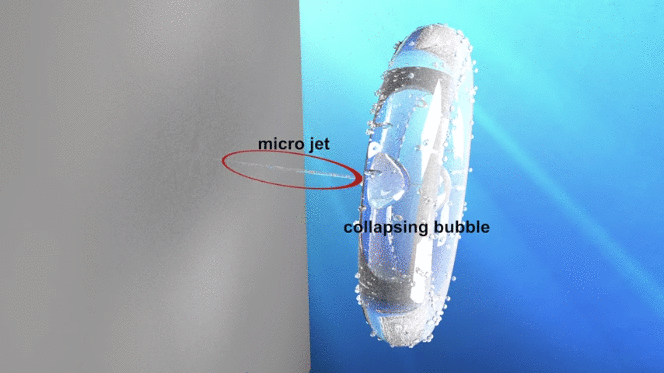
Video 1 shows the formation and collapse of a 9 mm diameter cavitation bubble in slow motion. In real-time, this whole process takes only four milliseconds. When it’s time to change its state, the bubble collapses, i.e. implodes and does not explode. Implosion happens because liquid water occupies volume many times lower than vapour.
The bubble collapses at its weakest spot. First, it assumes the shape of a ring, which transforms into a torus shape before it disintegrates completely, giving way to shock waves and a strong microjet.
Effects of cavitation
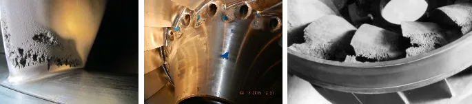
It is this micro jet that does all the damage. Micro jets are powerful enough to damage even high strength material. Implosions release packets of energy in a short duration concentrated at a micro spot. If a microjet hits a surface, it causes short term over-straining. It gradually leads to cavitation corrosion and cavitation damage. Over time, the material develops cracks with repeated bursts and eventually breaks off.
Thus cavitation in turbines is an unsteady phenomenon that triggers low-frequency pressure oscillations and high-frequency pressure pulses. The pressure oscillations are due to the cavity dynamics, while the pressure pulses are associated with cavity collapse. These sources of excitement that act inside the main flow or adjacent to walls generate vibrations and acoustic noise. When they propagate through the hydrodynamic and mechanical systems, it results in high vibrations, blade erosion and instabilities, ultimately leading to the destruction of the whole machinery.
There are different types of cavitations in turbines. They are usually categorized based on how they are formed, their structure, their motion in the fluid medium, etc.
Types of cavitation in turbines
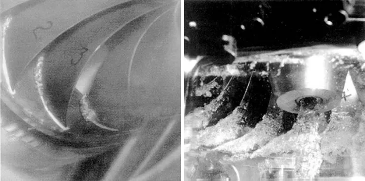
a. Leading-edge cavitation in turbines:
This type of cavitation is usually seen attached to the runner blades’ suction side. They are formed under operating conditions of high head and inflow incidence angles that are positively larger than the design value. They can also occur on the pressure side when operating at a low head and negative angle of incidence. If unstable, they provoke pressure fluctuations and can cause deep blade erosion.
b. Traveling bubble cavitation in turbines:
They take the form of separated bubbles attached to the blade suction side near the mid-chord, right next to the trailing edge. They are formed due to low plant cavitation numbers. They tend to gradually grow with an increase in load and attain maximum size when the machine operates in overload condition with maximum flow rate. These are severe and noisy types of cavitation that provoke blade erosion and significantly reduce machine efficiency.
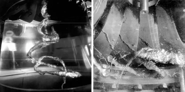
c. Draft tube swirl:
In this, cavities get created in the low-pressure central core of a vortex, formed just below the runner cone in the centre of the draft tube. The vortex appears at partial load and overload conditions due to the residual circumferential velocity component of the flow discharged from the runner. In some instances, they generate large bursts of pressure pulses in the draft tube, causing strong vibrations on the turbine and even on the powerhouse.
d. Inter-blade vortex cavitation in turbines:
These are formed by the secondary vortices located in the channels between the runner blades. They are created when flow separation occurs due to incidence variation from the hub to the band. Occasionally, they are seen even attached to the crown. These vortices appear at partial load conditions and are very noisy. Sometimes they are observed to occur at extremely high-head operation ranges. In such cases, they tend to be unstable and cause strong vibrations.
e. Von Karman vortex cavitation in turbines:
These are nothing but the periodic vortex shedding occurring from the trailing edges of the runner blade and vanes. Cavities develop in the low-pressure central cores of the vortices. This type of cavitation is known for generating severe pulsations and singing noise. In worst-case scenarios, they damage the blade trailing edges.
Cavitation can present itself in different forms depending on the operating conditions and machine design. Also, their occurrence depends on the system’s material properties and vibrational dynamics. Unfortunately, it is impossible to prevent or nullify it entirely but can only be reduced to a minimum acceptable level.
Trailing thoughts
Cavitation is a two-phase unsteady phenomenon, and numerical prediction of its formation in the design phase itself is an important task. Modern computing power with advanced two-phase modelling algorithms makes this possible – this was unthinkable a couple of decades ago. It is critically important to understand cavitation, especially cavitating vortex rope since they generate large pressure fluctuations, low-frequency vibrations, and undesirable variations in turbine output. CFD presents itself as the ideal tool to give insight into the cavitation flow characteristics even before the turbine is manufactured.
In the first two articles in the Series on Water Turbines, we have tried to cover the working mechanisms, flow physics and phenomenons like vortex rope and cavitation. In the next article in the series, Part 3 Influence of Meshes on Water Turbine CFD, we will be covering the modelling approaches and gridding aspects like grid refinement, mesh size, Y+, grid influence on CFD prediction, etc.
Water Turbine Series:
Part 1 – Understanding the flow through Francis turbine.
Part 2 – Cavitation in turbines.
Part 3 – Influence of Meshes on Water Turbine CFD.
Part 4 – Grid Convergence Study for Francis Turbine- From a Meshing Software Perspective.
References
1. “Detection of cavitation in hydraulic turbines”, Xavier Escaler et al, Mechanical Systems and Signal Processing 20 (2006) 983–1007.
2. ” Hydrodynamics of pumps“, Christopher E. Brennen et al, January 2011.
3. “Cavitation Detection Technology for Optimizing Hydraulic Turbine Operation and Maintenance“, U.S. Department of the Interior Bureau of Reclamation Research and Development Office, March 2018.
4. “Kaplan turbine tip vortex cavitation – analysis and prevention”, L motycak etal, 26th IAHR Symposium on Hydraulic Machinery and Systems, IOP Conf. Series: Earth and Environmental Science 15 (2012) 032060.
5. “Cavitation in Kaplan Turbines – A Review”, Munendra Kumar et al, Journal of Material Science and Mechanical Engineering (JMSME) Print ISSN: 2393-9095; Online ISSN: 2393-9109; Volume 2, Number 5; April-June, 2015 pp. 425-429.
6. “Turbine Repair”, William Duncan, Jr. FACILITIES INSTRUCTIONS, STANDARDS, & TECHNIQUES, VOLUME 2-5, September 2000.
7. “Cavitation in Hydraulic Turbines“, Ece Ayli, International Journal of Heat and Technology, Vol. 37, No. 1, March, 2019, pp. 334-344.
8. “Cavitation in Francis turbines“, Nirajan Khakurel, Master thesis, Aachen University of Applied Sciences,
Campus Jülich, December, 2015.
9. ” Numerical Investigations of Flow on the Kaplan Turbine Runner Blade Anticavitation Lip with Modified Cross Section“, Vasile Cojocaru et al, Recent Researches in Mechanics, ISBN: 978-1-61804-020-6.
10. Cavitation – Easily explained!
11. http://www.repairengineering.com/cavitation.html.
12. https://www.hydroreview.com/2018/06/01/overcoming-cavitation-through-collaboration/#gref.
13. https://www.eneconmesogios.com/index.php/project/262/german-utility-company-repairs-and-protects-cavitation-damage-on-francis-turbine-with-ceramalloy-dur