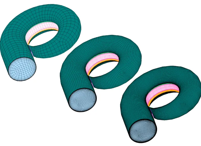
Figure 1: Sequential multi-block grids for a Francis turbine
1389 words / 7 minutes read
This is the 4th and final part of the series on Hydraulic Turbines:
Part 1 – Understanding the flow through Francis turbine.
Part 2 – Know the Flow – Cavitation in hydraulic turbines.
Part 3 – Influence of Meshes on Hydraulic Turbine CFD.
Part 4 – Grid Convergence Study for Francis Turbine- From a Meshing Software Perspective.
Prelude
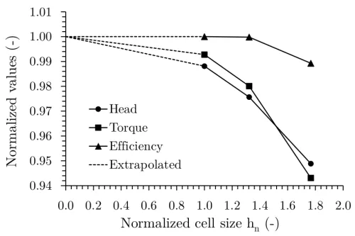
Over the years, grid convergence studies (GCS) has become one of the most authoritative CFD best practices to confirm the validity of computational results. The study framework involves analyzing the evolution of some response flow parameter or quantity like losses, power, force, local or global, to the progressive grid refinement. In a finite volume method, the truncation error is associated with the grid cell size. So, if we keep on reducing the cell size, the corresponding error should also reduce in a systematic way.
In the absence of an exact solution, it is not possible to calculate the solution error. Nevertheless, the convergence towards a value on an infinitely fine grid can be calculated by extrapolating the quantity obtained on a series of grids. This convergence behavior should happen on systematically refined grids.
Challenges in Generating Sequential Grids
In practice, it is observed that systematic refinement is hard to enforce especially with unstructured and automatic meshers like the cartesian gridding approach. Even with the structured multi-block approach, this precondition is unrealistic when using wall functions because of their incompatible requirements of first cell height at wall boundaries. This often results in an awkward situation where cells in the core flow become more refined than the cells at the wall. As a good gridding practice, it is advised to aim for the same relative density distribution in each refined grid.
CFD engineers mostly rely on structured grids for their hydraulic simulations even though it is often perceived that structured grid generation is a time consuming, labor-intensive task, demanding a high level of expertise to meet the somewhat indistinct requirements to attain good quality grids. On the other hand, unstructured gridding approach are also regularly used but are consigned to the most complex components of the hydraulic turbines like spiral casing where hand-crafting a structured multi-block grid is considered too costly to justify.
Many structured generators which are good to generate arbitrarily complex multi-block grids demand larger human involvement when addressing newer configurations or for adjusting the nodal distributions. Semi-automatic multi-block meshers are also used for GC studies which can quickly generate high-quality meshes with few parameters. Unfortunately, they too have limitations in managing the cell distribution accurately and creating uniformly refined grids. Often it so happens that the engineer is compelled to change certain meshing parameters which even though end up in generating a valid grid with acceptable mesh quality but they fail to qualify to be part of a progressively refined grid family.
The following section gives some detail of generating sequential grids for a Francis turbine using GridPro.
Sequential Grids in GridPro
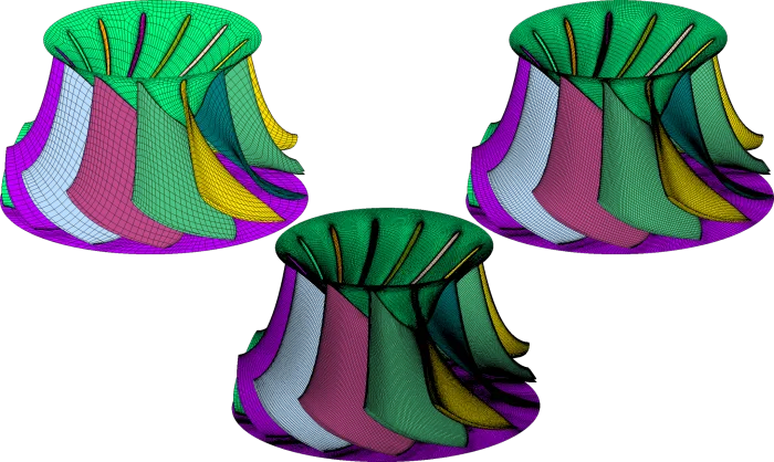
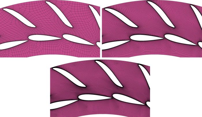
Generating systematically refined grids in GridPro is relatively easy. Whether it is for an individual component like a runner with blade and splitter or the complete hydraulic turbine involving spiral casing, stay vanes, guide vanes, runner and draft tube, the steps involved in generating sequential grids is just the same.
To begin, a good topology involving all the components of the turbine is built and the first base grid is generated. Next, to get subsequent grids with hierarchical refinement, the topology block density or grid block densities are modified in an orderly fashion in all three coordinate directions. In a nutshell, the philosophy followed is – one topology, multiple grids with zero modification to the base topology.
So, as one can institutively guess, most of the human effort and time go in getting that good initial topology. Much to the relief of the meshing engineer, the pain point of building topologies for complex geometries is considerably reduced by the dynamic boundary conforming blocking concept adopted in GridPro. Users need not handcraft the blocks but rather provide a loose pattern of blocks representing the topology of the geometry, the sophisticated block building tools in GridPro rapidly fill the domain.
Once the base topology is ready, getting the sequential grids tiny, coarse, fine, extra-fine and ultra-fine is easy. Using the base topology, the grid family can be generated in any of the three approaches namely – by changing the block edge density, by reducing the grid density and by using the schedule file.
In the block edge density modification approach, the edge density in the wireframe is systematically increased in the x, y and z-direction for each block. So, for every member of the grid family, the edge density modification is done and the grid generator is run to get the grid. To start, the block densities are set to obtain the coarsest grid first. For the subsequent grids, the block density is increased in multiples of 3X.
In the second approach, the grid family is built in the reverse order. First, the finest grid is generated and then the rest of the grids are derived by plucking out alternative grid lines from this fine grid. Since this approach involves only postprocessing the generated first grid, it is relatively faster than the first approach.
The third approach of using a schedule file is convenient for generating grids in production mode. In fact, all the grids can be generated in an automation mode using the schedule file. In the schedule file details like grid density, first cell height, growth rate and the number of layers in the boundary layer padding are provided. When the grid generator is run through the command line, it picks up the inputs from this schedule file and generates grid accordingly. By controlling the inputs for the schedule file through a batch script, the grid family can be built with no intervention.
The topology creation can also be hastened up by the semi-automatic tools available in GridPro. For example, the tool called copy by reference can create blocks the entire circumferential length of the spiral casing at one go. This is done by sweeping a 2D wireframe along the volute contour and intermittently adding an appropriate number of inserts. With a little bit of manual intervention, the topology for the volute can be created in surprisingly record time.
Similarly, other tools like copy and reflect can speed up the block creation for distributor and runner. A periodic topology can be created for one set of stay vane and guide vane or a runner with one blade and splitter. Once completed, the entire distributor or runner can be topologized by copying and reflecting.
Further, local compact blocks without block fineness propagation can be created in critical regions. Finer blocks can be placed with ease at critical locations by tools like Enriching, while tools like nesting help to rapidly coarsen out as we move away towards the domain boundaries. In a way, the options in GridPro bring home the best in both structured and unstructured approaches.
In fact, the entire topo building can be whipped up if we have a team of meshers. What can be done is, topo for each component can be created by each individual and later once completed, can be assembled together and stitched up. Since all the components are radially placed to each other, by adding or removing block sheet inserts to match the block count between different components, stitching can be done swiftly and effortlessly. This approach will bring down the topology building time for hydraulic turbines massively.
One highlighting aspect of the sequential grids generated by GridPro is the consistency of mesh quality across the grid family. The grid generator ensures that the critical quality parameters like surface folds, volume folds, skewness, minimum angle are within an acceptable range.

Parting Remarks
Inspite of the great progress made over the last two decades, making consistent reliable CFD predictions of flows in hydraulic turbines is still a challenge. The crux of the issue lies with the assessment of the solution accuracy. GCS are an effective way to check the independence of the solution from the grids, discretization errors and also in obtaining valuable insight into actual solution accuracy.
However, conducting such studies for complex flow fields with detached flows like in hydraulic turbines often comes with many challenges including the need for huge computational resources and difficulties in generating progressively refined grids. Nevertheless, it is instructive to conduct such studies as multiple grids asymptotically converging to the same data point greatly reinforces the credibility of the CFD results.
This brings us to the end of the 4th and final Part of the series on Hydraulic Turbines. The previous 3 articles in the series can be accessed through the links provided below.
Hydraulic Turbine Series:
Part 1 – Understanding the flow through Francis turbine.
Part 2 – Know the Flow – Cavitation in hydraulic turbines.
Part 3 – Influence of Meshes on Hydraulic Turbine CFD.
Part 4 – Grid Convergence Study for Francis Turbine- From a Meshing Software Perspective.