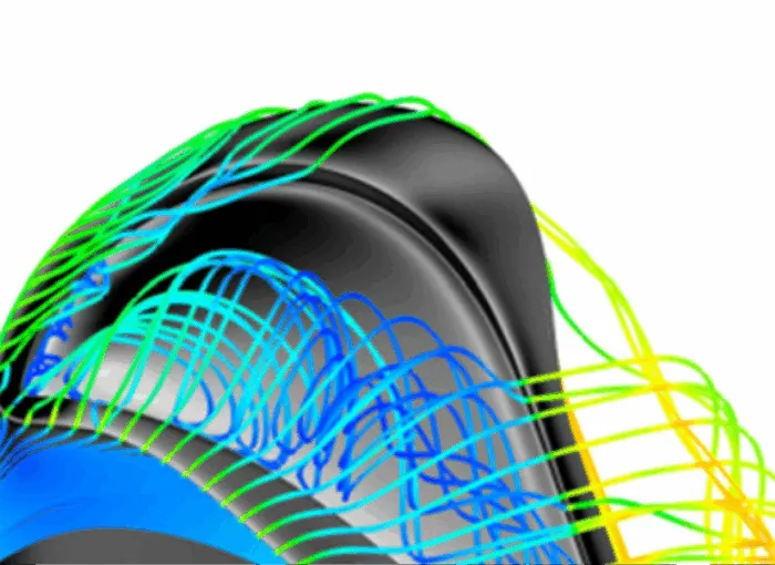
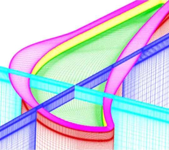
Figure 1: Turbine blade with winglet tips – 3D streamlines. Image source – Ref [1].
702 words / 3 minutes read
Winglet Tips are effective design modifications to minimize tip leakage flow and thermal loads in turbine blades. A reduction in leakage losses of up to 35-45 % has been reported.
Introduction
The design and optimization of gas turbines is a crucial aspect of the energy industry. One aspect that has gained significant attention in recent years is the issue of tip leakage flow in gas turbines. Tip clearances, which are provided between the turbine blade tip and the stationary casing, allow free rotation of the blade and also accommodate mechanical and thermal expansions.
However, this narrow space becomes instrumental in the leakage of hot gases when the pressure difference between the pressure side and the suction side of the flow builds up. This is undesirable as it reduces the turbine efficiency and work output. According to some studies, tip leakage loss could account for one-third of the total aerodynamic loss in turbine rotors. Further, leakage flows bring in extra heat, which raises the blade tip metal temperature, thereby increasing the tip thermal load.
It is, therefore, essential to cool the blade tip and seal the leakage flow. Over the years, various design features have been proposed as a solution. One of the promising features employed in tip design is the use of winglets.
Turbine Blade Winglet Tips
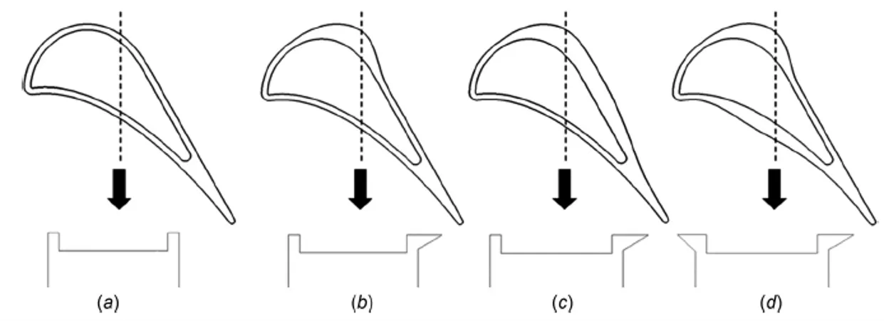
Winglet tips comprise of a blade tip with a central cavity and an outward extension of the cavity rim called the winglet. Different variants are developed based on the outward extent of the winglet, the length of the winglet and the location of the winglet. Figure 3 shows three winglet variants derived from the base geometry of the tip with a cavity. The first two have winglets on the suction side with different lengths, while the third one has a small winglet on the suction side as well as on the pressure side.
Tip Flow Structure
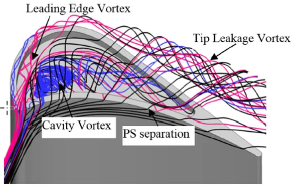
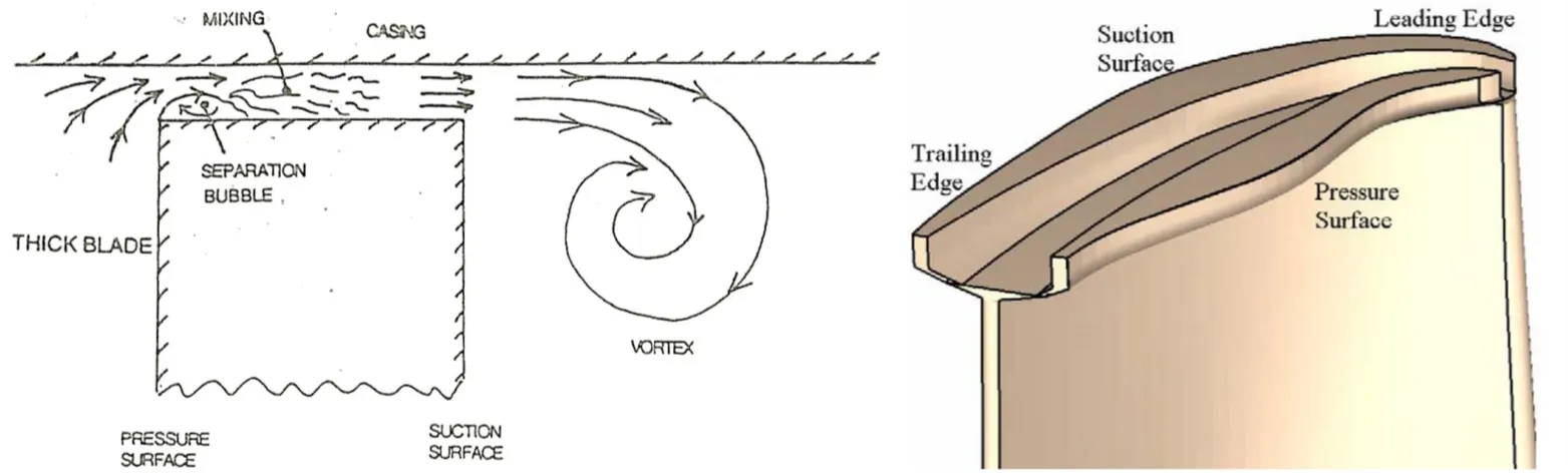
The flow pattern within the cavity of the winglet-cavity tip is similar to that in the cavity tip. On the blade pressure surface, the flow accelerates toward the trailing edge. On the blade suction surface, the flow accelerates till 60 percent of the tip chord and then decelerates toward the trailing edge. Near the leading edge of the blade tip, the flow enters the tip gap and impinges on the cavity floor of the tip, enhancing the local heat transfer. Then, a vortex forms along the suction side squealer. The vortex within the cavity is called a “cavity vortex.” It is also observed that the flow separates at the pressure-side tip edge, and most of the fluid exits the tip gap straight after entering the tip gap from the pressure-side inlet. Nevertheless, some fluid entering the tip gap mixes with the cavity vortex first and then exits the tip gap. The tip leakage flow exiting the gap rolls up to form a tip leakage vortex.
Meshing Winglet Tips
While generating meshes for leakage flow simulations, having a fine mesh in the leakage gap is critical. The narrow gap should be finely resolved with at least 40-50 layers of cells. In the tangential direction across the tip gap, 30 – 40 layers of cells are required to capture the winglet width and 150-160 cell layers to capture the tip gap from the suction side to the pressure side. Such a fine-resolution structured mesh will lead to a total cell count of about 7 to 9 million.
The boundary layer should be fully resolved with an estimated Y+ less than 1, using a slow cell growth rate of 1.1 to 1.2. Grid refinement studies with grids varying from 6 to 10 million have shown to decrease the tip average heat transfer coefficient by about 1.8 to 1.9% with every 2 million increase in cell count.
Conclusion
The average tip heat transfer coefficient (HTC) and total tip head load increase with an increase in tip gap. HTC is observed to be high on the pressure side winglet due to flow separation reattachment and also high on the side surface of the suction side winglet due to impingement of the tip leakage vortex.
Tip winglets are found to decrease tip leakage losses. Because of the long distance between the two squealer rims, the flow mixing inside the cavity is enhanced, and the size of the separation bubble at the top of the suction side squealer is increased, effectively reducing leakage loss. In a low-speed turbine, the winglet cavity tip is observed to reduce loss by 35-45% compared to a flat tip. When it comes to thermal performance, the tip gap size becomes a major influencing factor.
Other Articles in the Series
- Innovative Turbine Blade Tips to Reduce Tip Leakage Flow.
- Effective Control of Tip Vortices Using Squealer Tips.
- Honeycomb Tips to Reduce Turbine Leakage Flows.
Further Reading
- The Art and Science of Meshing Turbine Blades
- Efficient Meshing of Turbine Blade Cooling Holes!
- Turbopumps – A Unique Rotating Machine
Reference
1. “Heat Transfer of Winglet Tips in a Transonic Turbine Cascade”, Fangpan Zhong et al., Article in Journal of Engineering for Gas Turbines and Power · September 2016.
2. “Tip gap size effects on thermal performance of cavity-winglet tips in transonic turbine cascade with endwall motion”, Fangpan Zhong et al., J. Glob. Power Propuls. Soc. | 2017, 1: 41–54.
3. “Turbine Blade Tip External Cooling Technologies”, Song Xue et al., Aerospace 2018, 5, 90.
4. “Aero-Thermal Performance of Transonic High-Pressure Turbine Blade Tips“, Devin Owen O’Dowd, St John’s College, PhD Thesis, Department of Engineering Science, University of Oxford, 2010.