
Figure 1: Turbine blade with squealer tips.
1005 words / 5 minutes read
Squealer tips solve various challenges in the turbine blade tip gap region, such as reducing tip leakage flow and protecting blade tips from high-temperature gases. Further, they also improve design clearance through their sealing properties.
Introduction
To improve turbine aerodynamic performance, reducing tip leakage loss is important. However, due to the existing radial gap between the rotating blades and the stationary casing, tip leakage flow is inevitable. When the leakage flow mixes with the main flow, leakage losses occur, which can be as large as one-third of the total blade passage loss. This huge loss highlights the importance of controlling tip leakage loss for the efficient operation of turbines.
Efforts to minimize tip leakage losses are carried out by improving blade tip designs. Turbine blades come in two types – shrouded and unshrouded. It is in unshrouded blades where this tip leakage loss is prominent. So, many tip shape designs like flat tips, squealer tips, tips with winglets and honeycomb cavities, etc., are developed to reduce leakage loss. Out of these, squealer tips have gained the most attention because of their excellent aerodynamic performance.
Unfortunately, less clarity exists in understanding the dominant flow structure, which affects the aerodynamic benefits of the squealer tip. Hence, numerical and experimental studies are conducted to study the effects of different tip designs on the aerodynamic performance and cooling requirements.
Squealer Tip Variants

Squealers comprise a boundary rim encircling the blade tip periphery and a central cavity. While doing parametric geometry optimization, the rim thickness and the cavity depth are varied to generate different variants, as shown in Figure 2a.
Squealer variants are also generated by varying the rim length along the blade tip periphery. Partial rims on the suction side are called suction-side squealers, and those on the pressure side are called pressure-side squealers, while squealers with rim running all along the tip periphery are called double-side squealers or simply squealers. Figure 2b shows this class of squealers.
Each variant uniquely modifies the flow to bring in favourable performance benefits. Moving from left to right in Figure 2a, the blade heat-flux increases with an increase in efficiency. Design A, with the rim removed at both the leading edge and trailing edge of the blade, provides the lowest heat flux. Design B, with increased suction side rim length, provides increased efficiency, while Design C, which is nothing but Design B with winglets or overhang, provides the highest efficiency.
The opening at the LE and TE bring in beneficial effects. The opening at the TE increases the strength of the cavity vortex and improves its sealing effectiveness. On the other hand, the opening at the LE allows some flow to enter the cavity, reducing the angle mismatch between the leakage and the main flow. Overall, the combination of LE and TE openings has a positive effect on heat transfer.
Flow Physics Around Squealer Tips
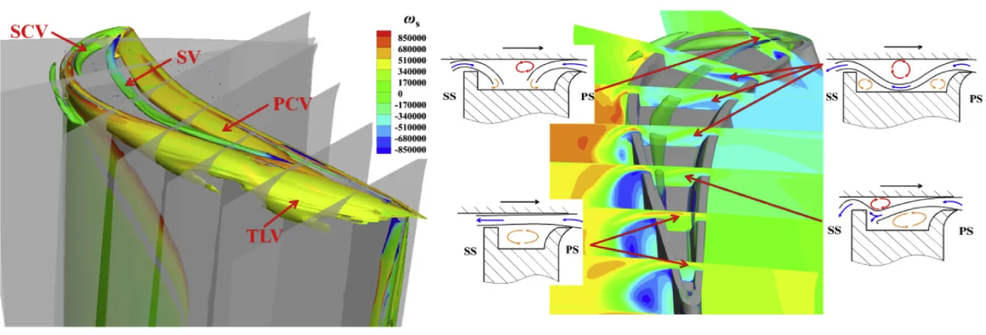
The squealer tip cavity is home to many vortices, such as the cavity vortex, scraping vortex and the corner vortex. When these vortices’ characteristics change, they alter the mixing of leakage flow inside the cavity and the separation bubble at the top of the suction side squealer. This modifies the controlling effect of the squealer tip on the leakage flow.
Out of the many vortices, the scraping vortex is the most dominant flow structure, which plays a critical role in leakage loss reduction. It forms an aero-labyrinth-like sealing effect inside the cavity. Through this effect, the scraping vortex increases the energy dissipation of leakage flow inside the gap and reduces the equivalent flow area at the gap outlet. The discharge coefficient of the squealer tip is therefore decreased, and the tip leakage loss is reduced accordingly.
So when we vary the blade tip load distribution and also the squealer geometry, the scraping vortex characteristics, such as the size, intensity and position inside the cavity, change, resulting in a different controlling effect on leakage loss.
Geometrically, the squealer height also matters. It has an optimum value, and any deviation from it will cause a reduction in the size of the scraping vortex, leading to lesser effectiveness in controlling the leakage loss.
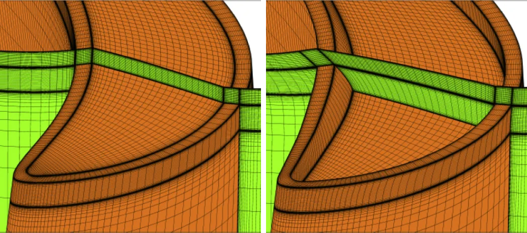
Meshing the Squealer Tips
Usually, hexahedral meshes are preferred for turbine blade simulations because of their low dissipation quality. An H-type topology is used for the main regions of the computational domain, while an O-type topology is used in the near vicinity of the blade wall and inside the tip gap. When doing simulations for multiple squealer tip variants, it is better to use the same topology and do minimal alteration only if needed to avoid numerical discrepancy.
The boundary layer needs to be fully resolved with Y+ less than one. Since the tip gap is the source for vortex generation, recirculation, flow separation and reattachment, it is quintessential to have a high resolution of the tip gap. Also, the point placement on the blade near the tip in the spanwise direction is made finer.
Before undertaking an optimisation study to find the best-performing squealer variant, it is better to conduct a grid independence study to eliminate the grid effect on the solution and also to converge on the optimal mesh number. Firstly, since the tip gap is of utmost importance, the radial mesh in the gap can be varied from 10 to 50 and analysed.
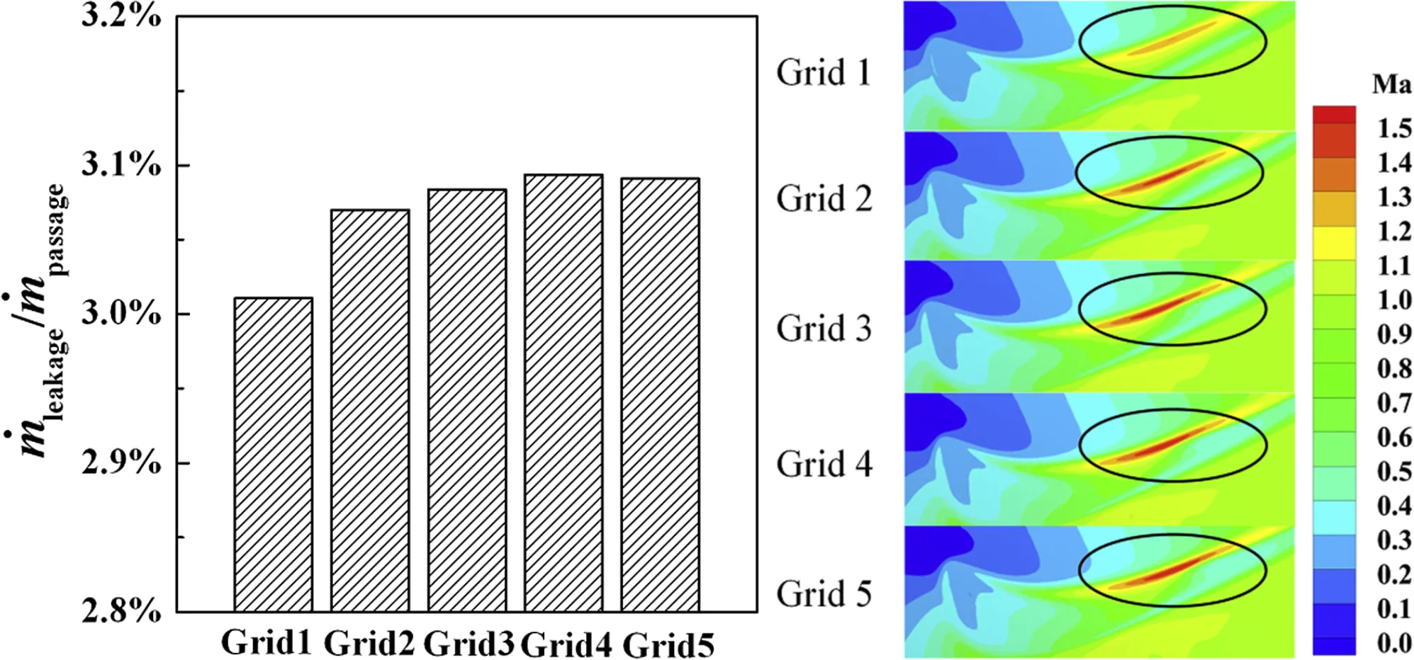
Figure 5a shows one such analysis where the difference in leakage flow rates is observed to be becoming smaller with an increase in mesh number. When the mesh number exceeds that of Grid 4, the change in leakage flow rate is less than 0.3%.
Figure 5b shows the flow field in the middle of the gap. As can be observed, the flow field in the gap doesn’t change beyond level Grid 4 refinement, with about 37 layers in the gap.
outlet. Image source – Ref [1].
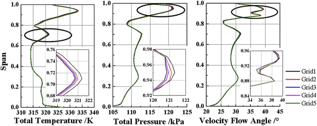
Figure 6 shows another plot of solution variation with grid refinement at the rotor outlet. With the increase in gap mesh numbers, the numerical discrepancies caused by different mesh numbers are gradually reduced. Carrying out such similar grid-independent analyses at other positions and directions will help us to converge on to a mesh with optimal refinement at all critical locations.
Conclusion
Squealer tip serves as an effective tool in reducing tip leakage flow. They also protect the blade tips from the full impact of the high-temperature leakage gases. Lastly, they act as a seal and help in achieving a tighter design clearance in the tip gap region.
By making a reasonable choice in geometric parameters and proper blade loading distribution, the scraping vortex in squealer tips can be better regulated to reduce tip leakage flow.
Other Articles in the Series
- Innovative Turbine Blade Tips to Reduce Tip Leakage Flow.
- Cooling the Hot Turbine Blade with Winglet Tips.
- Honeycomb Tips to Reduce Turbine Blade Leakage Flows.
Further Reading
Reference
1. “Dominant flow structure in the squealer tip gap and its impact on turbine aerodynamic performance”, Zhengping Zou et al., Energy 138 (2017) 167-184.
2. “Numerical investigations of different tip designs for shroudless turbine blades”, Stefano Caloni et al., Proc IMechE Part A: J Power and Energy 2016, Vol. 230(7) 709–720.
3. “Aerodynamic Character of Partial Squealer Tip Arrangements In An Axial Flow Turbine”, Levent Kavurmacioglu et al., 200x Inderscience Enterprises Ltd.
4. “Aerothermal and aerodynamic performance of turbine blade squealer tip under the influence of guide vane passing wake”, Bo Zhang et al., Proc IMechE Part A: J Power and Energy 0(0) 1–20.