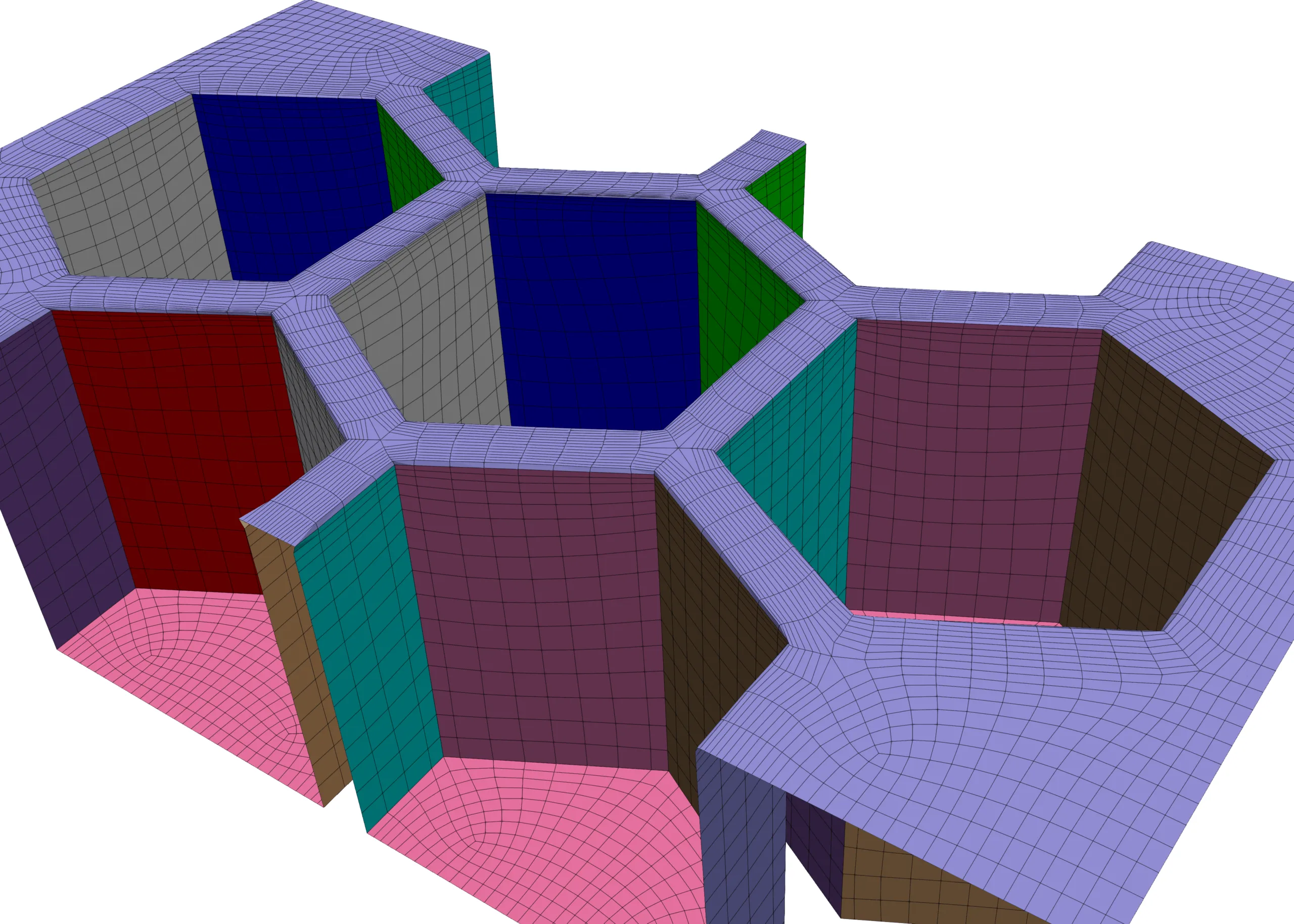
Figure 1: Structured mesh for honeycomb cells using GridPro.
475 words / 2 minutes read
Honeycomb tips offer a promising solution for mitigating tip leakage flows in turbines. These novel tip designs have shown to be highly effective in reducing tip leakage mass flow rate and aerodynamic losses, outperforming conventional flat tips.
Introduction
The design of turbine blades, particularly the tips, plays a significant role in determining the efficiency and performance of turbines. Although an unavoidable issue, tip leakage flow can lead to reduced tip loads and increased aerodynamic losses through flow separation and mixing. With the increasing loads handled by high-performance turbines, the intensity of tip leakage flow becomes even more pronounced. To address this, new designs or improvements to existing designs are necessary. One promising solution is using honeycomb tips, which have proven to be effective in reducing the negative effects of tip leakage flow. This article will delve into the advantages of honeycomb tips and how they can improve the performance of high-performance turbines.
Honeycomb Tips
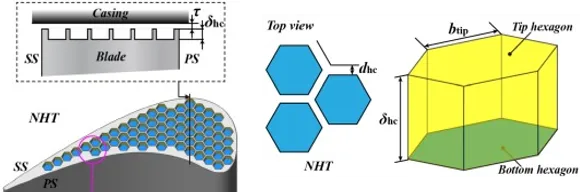
The concept of honeycomb tips is a relatively new and innovative approach to blade tip design. This design features multiple hexagonal cavities on the blade tip, usually numbering 60-70 and with a depth of a few millimeters.
Research has revealed that honeycomb tips have favourable characteristics for inhibiting tip leakage flow. Part of the leakage flow enters the hexagonal cavities and creates small vortices. These vortices mix with the upper leakage fluid, which leads to an increase in resistance in the clearance space, suppressing the tip leakage flow and reducing the size and intensity of the leakage vortex. Additionally, the use of honeycomb tips allows for a tighter build clearance compared to a flat tip, as contact is less damaging.
Honeycomb Tip Design Variants
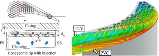
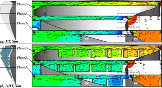
There are various modifications to the standard design of honeycomb tips. One such variation involves injecting coolant from the bottom of each hexagonal cavity to enhance heat transfer at the blade tip. Simulations have demonstrated that this design results in a reduction of up to 26.7% in the tip leakage mass flow rate and a decrease of approximately 4.6% in the total pressure loss coefficient compared to a flat tip.
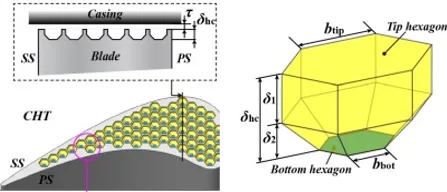
Another variation of honeycomb tips is the composite honeycomb tip, which features an additional lower frustum in addition to the upper hexagonal prism. Studies have indicated that this design leads to a reduction of up to 16.81% in the tip leakage mass flow rate and a decrease of 5.49% in losses.
Thus, both variations of honeycomb tips show great promise in significantly enhancing the performance of turbine blades.
Meshing the Honeycomb Tips
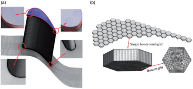
To effectively capture the effects of these tiny honeycomb cavities, finely resolved mesh is essential. The boundary layer needs to be fully resolved with Y+ around 1. With 60-70 cavities, the total cell count could reach 5-6 million, with each cavity requiring about 0.0075 million cells for proper discretization. Such a fine mesh is necessary to precisely capture the tip vortex and the small cavity vortices, as well as the interactions between them.
Conclusion
Honeycomb tips offer a promising solution for mitigating tip leakage flows in turbines. These novel tip designs have proven to be highly effective in reducing the tip leakage mass flow rate and aerodynamic losses, outperforming conventional flat tips. The cavity vortices created within the honeycomb design effectively control the leakage flow, making it a viable option for various clearance gaps. Overall, honeycomb tips have the potential to significantly improve the performance of turbines.
Other Articles in the Series
- Innovative Turbine Blade Tips to Reduce Tip Leakage Flow.
- Effective Control of Tip Vortices Using Squealer Tips.
- Cooling the Hot Turbine Blade with Winglet Tips.
Further Reading
References
1. “Effect of clearance height on tip leakage flow reduced by a honeycomb tip in a turbine cascade”, Fu Chen et al., Proc IMechE Part G: J Aerospace Engineering 0(0) 1–13.
2. “Effect of cooling injection on the leakage flow of a turbine cascade with honeycomb tip”, Yabo Wang et al., Applied Thermal Engineering 133 (2018) 690–703.
3. “Parameter optimization of the composite honeycomb tip in a turbine cascade”, Yabo Wang et al., Energy, 22 February 2020.