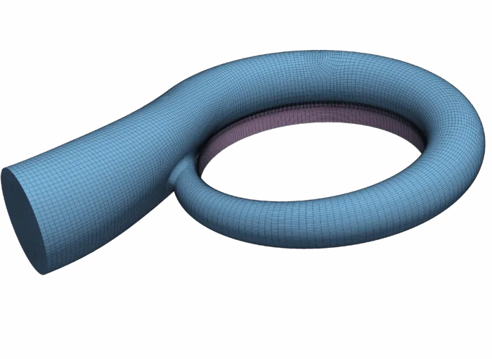
Figure 1: Structured multi-block meshing of a volute.
2200 words / 11 minutes read
Introduction
With the increase in stricter pollution policies, eco-conscious customers, the demand for low carbon emission and energy-saving vehicles is steadily growing. With electric vehicles been the rage of town, the fossil fuel-driven automotive industry has upped its ante by building highly efficient and downsized engines. This has been made possible by the improvements in turbochargers design. Turbochargers enable a significant reduction in internal combustion engine size, reduce fuel consumption and emission levels. Further, they also increase the engine rate, the limiting torque curve, and the torque back-up.
Over the years, the understanding of the flow field and design of turbochargers has improved considerably. A major part of the industrial effort has been to increase the performance and reduction of losses in the impellers and vaned diffusers of the compressor and the turbine in turbochargers. However, insufficient attention has been paid to the flow diffusion in the compressor volutes, the losses incurred, and the influence of volutes on the overall performance of the compressors.
With the latest trend for compact engines and installation constraints, manufacturers are forced to reduce the turbocharger size. This means compact volute designs with the flow leaving the volute exit with considerable kinetic energy. Hence a more careful evaluation of the flow diffusion, ways to reduce losses, and improve performance by understanding the influence of geometric parameters in volutes is certainly needed.
Why volute design is important?
The flows inside volutes are complex and multiple parameters influence them. Hence, it is no wonder that there is little consensus among designers as to what an optimized volute geometry looks like. Adding to this lack of clarity, volutes designed by different approaches give different pressure ratios and efficiency.
Extensive research work has gone into understanding and improving impellers and vaned diffusers in compressors and turbines. On the contrary, volutes are the least investigated and less understood component. Yet this part plays an important role in the compressor’s functioning.
The volutes strongly influence the compressor’s overall performance, stability limits, operating range, and pressure distortion at off-design conditions. Further, rather than the impeller, volutes determine the location of the point of best efficiency of the compressor.
Small changes in volute design can have a significant global impact on the performance of the compressor. For example, shortening of the volute tongue can impact the volute performance which in turn influences the global performance of the radial compressor. Or for that matter, the dilemma w.r.t the choice of volute geometry – symmetrical or overhung, makes design decisions perplexing. These design issues are just the tip of the iceberg, one will confront while designing volutes.
Hence, it is critically important to understand the influence of design parameters on volute and compressor performance. Also, even though the loss in volutes is less telling than that in the impeller or vaned diffusers, the potential for improvement is still sizable. Any small reduction in losses by design modifications does make a meaningful impact.
Lastly, flows in turbocharger centrifugal compressors by definition are non-axisymmetric due to the asymmetric nature of volute geometry, especially in off-design conditions. This results in the generation of pressure distortions in a circumferential direction which worsens the compressor’s stability and performance. This is a critical issue and it needs some serious attention.
Knowing the current trend in internal combustion engine downsizing, the stability of turbocharger centrifugal compressors is a major worrying issue. Since these pressure distortions are produced in the volutes, its design has lately gained larger attention as it considerably affects turbocharger performance.
Volute induced circumferential pressure variation
Volutes, for smaller mass flow rates, acts as a diffuser. This causes a rise in static pressure from the tongue to the volute exit. However, at larger mass flow rates, the volute becomes too small and the flow accelerates from the tongue to volute exit.
Back pressure disturbances develop in the volute more specifically at the tongue region, which propagates upstream and influences the flow at the diffuser and impeller exit. This results in extra losses and pressure distortions around the impeller periphery. Further, these pressure distortions reduce the stage performance and have a direct impact on the impeller and diffuser flow stability.
An offset of the development of circumferential pressure distortion is the creation of radial forces on the impeller shaft, which sometimes lead to failure of the shaft bearings. Also, the circumferential non-uniformity of the flow at the impeller exit causes mixing losses in the diffuser. And lastly, this cyclic variation in the impeller channels at each rotation results in additional energy dissipation.
The repercussions of these pressure fluctuations caused by the volute-impeller interaction can be felt through elevated levels of noise and vibration. This is especially so near the tongue region. Hence, understanding the flow field distortion and ways to modify the volute design to reduce this distortion is of critical importance.
Influential volute geometric parameters

A number of volute’s geometrical parameters influence the compressor’s performance, stability, and operating range. Out of an array of parameters, 5 parameters namely, cross-sectional area distribution, cross-sectional shape, the radial position of cross-section, location of volute inlet, and tongue geometry, have been recognized by many researchers as the major influential ones.
These parameters are related to the flow characteristics and losses inside the volute and hence directly impact the overall compressor performance. The following sections elaborate on these geometrical parameters in greater detail.
Cross-sectional area distribution
Studies have shown that volutes with cross-sectional area increasing circumferentially display better efficiencies and pressure ratios when compared to constant area cross-sections. In particular, linear increase in area provides the best head and efficiency. This is because volutes with increasing area produce uniform pressure distribution at design conditions. However, at off-design conditions, large pressure distortions are observed.
At low flow rates, the volute cross-sectional area is large. As a consequence, the flow initially decelerates causing a rise in static pressure, but later at the tongue, the pressure drops suddenly. On the other hand, at very high flow rates, the volute area is too small which causes a decrease in pressure as the fluid accelerates in the circumferential direction, but later at the tongue, the pressure suddenly increases.

Moving further, if we just consider the change in cross-sectional area, studies reveal that at low flow rates, a larger volute cross-sectional area significantly decreases the maximum rise in pressure coefficient but increases the maximum flow coefficient of the compressor. Further, the maximum efficiency reduces by up to 2% with the increase in area, and it gets shifted to higher flow rates.
Cross-sectional shape
The shape of the cross-section has an influence on volute losses. On closer observation, it is seen that modification in cross-section shape affects the operating range more than the peak efficiency. Volutes with various shapes including circular, semi-circular, elliptic, rectangular, and square have been experimented with and their influence closely assessed.
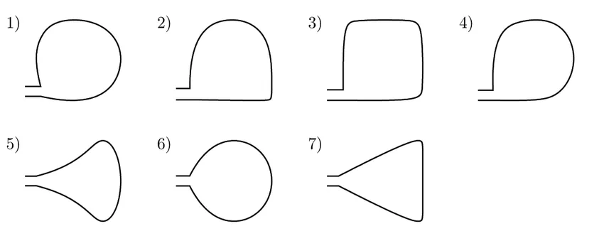
Out of these different cross-sections, volutes with circular cross-sections exhibit lower wall friction and mixing losses as they have a smaller wetted area. Also, it is observed that, with circular cross-sections, it is possible to eliminate the secondary vortices developing inside the volute.
Volutes with square or rectangular sections being easy to manufacture are often used. However, volutes with square cross-sections are worst than circular ones as they have increased flow losses. For the same reason, the rectangular sections are inferior compared to square cross-sections.
Location of volute inlet
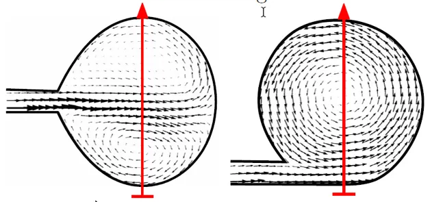
Studies experimenting with volute inlet location have shown that tangential inlets ( Figure 5b ) are more efficient compared to symmetric volutes ( Figure 5a). It is observed that asymmetrical shapes provide a larger stable operating range, higher mass flow rate, and higher pressure coefficient.
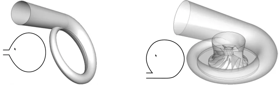
The reason for this is, tangential inlets produce a single vortex while symmetric volutes produce a double vortex structure. When there is a double vortex, the distance between the opposite flow direction is reduced and the radial velocity gradients also increase close to the diffuser outlet. Both these effects result in an increase of shear stress and hence higher losses in symmetrical volutes.
Radial position
Variation in the radial position of the volute channel results in an increase or decrease in losses thereby influences the compressor performance. From the principles of conservation of angular momentum, tangential velocity in a swirling flow is inversely proportional to the radius. If in a volute, the volute channel is positioned above the diffuser at a radius smaller than the diffuser outlet, then the tangential velocity inside the volute channel is higher than that at the diffuser outlet. This results in additional losses and undesired static pressure drop.
If we keep the cross-sectional shape and circumferential variation of the cross-sectional area constant and only increase the volute channel to a larger radius, a reduction in loss coefficient of up to 30% is observed.
On the other hand, for an internal volute with a cross-section radius smaller than the diffuser exit radius, a high loss-coefficient is observed for the entire operating range. In fact, the losses are very high as in collectors.
Further, it is noticed that a small variation in the radial position of the volute tongue w.r.t exit diffuser cone has an impact on the global efficiency of the volute. An increase in the radial position of the volute tongue increases efficiency.
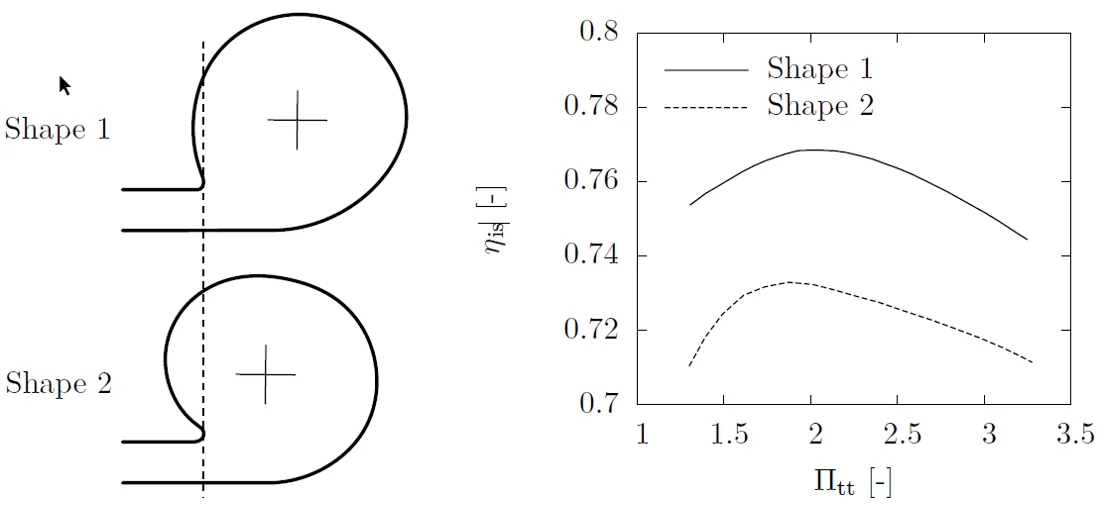
Asymmetric vs symmetric
Volute positional variations in the axial direction are usually presented as symmetric volutes and overhung volutes. For applications like the aerospace field where installation constraints such as space and weight are high, overhung volutes are employed.

Experiments and CFD simulations have shown that asymmetric volutes exhibit higher efficiencies than symmetric ones. This is because symmetric volutes are vulnerable to larger blockages at the inlet due to the generation of double swirl vortices. Also, a much stronger mixing process is observed to occur in symmetric volutes than overhung volutes, leading to higher losses.

When compared with forward and symmetry volutes, backwardly installed volutes (overhung volutes) show lower total pressure loss and higher static pressure recovery. Also, the speed asymmetry coefficient in backwardly installed volute exit is also slightly higher than that at the forwardly or symmetry-installed volute exits. Further, the backwardly installed volute has a more reasonable and uniform velocity field and better overall performances under different conditions. This is mainly because of the non-uniform outlet flow at the diffuser.
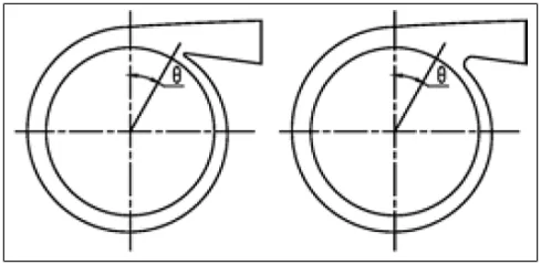
Tongue or lip shape and location
The radial clearance between the volute tongue and the impeller has a significant impact on the pressure distribution inside the volute and hence on the stage performance. Usage of a larger radial clearance distance leads to a reduction in interaction between the volute tongue and impeller. This helps in forming a better smoothened circumferential pressure variation in the tongue region.
However, increasing the radial clearance increases the recirculating flow in the gap between the tongue and the impeller and decreases the volute exit cross-section.
Normally, a volute with zero clearance gives a good volute performance at the design point. However, they are less adaptive to flow condition variations. Smoothening the leading edge of the volute tongue or in other words, providing a radial clearance helps the volute to achieve better efficiencies and stable flow range under off-design conditions also.
To know the optimal radial clearance for the entire flow range for a volute, the gap clearance can be modified either by changing the length of the tongue or by changing the tongue angle. In other words, the position and shape of the tongue become the influencing geometric variable affecting the machine performance. Rounding and retracting the tongue (shortening the tongue) increases the machine head and compression ratio at low and high flow rate conditions. Furthermore, many research authors have reported a significant reduction in noise levels and unbalanced aerodynamic forces when the tongue is moved away from the impeller.
Parting remarks
A good amount of studies have been done to understand and quantify the role of these 5 major volute geometric parameters and other minor variables. But, further research work is needed to get further clarify and appreciation for the role of geometric parameters in influencing volute flows. With the availability of parametric modeling software like Caeses and component-specific structured meshing software like Gridpro, a multitude of geometric variants can be build and meshed in an automated environment and CFD simulations performed. With parametric modeling, the level of influence of each of the geometric parameters can be brought out more clearly and accurately. Maybe, after conducting such optimization modeling exercises by independent researchers and organizations, it should be possible to have some general consensus as to what an optimized volute would look like.
Further reading
- Enhancing Turbocharger Efficiency with CFD and Automated Meshing Tools
- Automated Hexahedral Meshing of Gerotor Pumps
- Automated Hexahedral Meshing with GridPro: Structured Meshes for Parametric Geometry Variants
References
1.“Genetic Algorithm Optimization of the Volute Shape of a Centrifugal Compressor”, Martin Heinrich et al, International Journal of Rotating Machinery, Volume 2016, Article ID 4849025, 13 pages.
2. “Effect of inlet configuration and pulsation on turbocharger performance for enhanced energy recovery”, Jose Francisco Cortell Forés et al, PhD thesis, Department of Mechanical Engineering Imperial College London JUNE 2018.
3. “Experimental studies on volute-impeller interactions of centrifugal compressors having vaned diffusers”, Christos Georgakis, PhD Thesis, Academic year 2003.
4. “Unsteady behaviours of a volute in turbocharger turbine under pulsating conditions”, Mingyang Yang et al, JOURNAL OF THE GLOBAL POWER AND PROPULSION SOCIETY, 2017, 1: 237–25.
5. “An investigation of volute cross-sectional shape on turbocharger turbine under pulsating conditions in internal combustion engine”, Mingyang Yang et al, Energy Conversion and Management 105 (2015) 167–177.
6. “The Impact of Volute Aspect Ratio on the Performance of a Mixed Flow Turbine”, Samuel P. Lee et al, Aerospace 2017, 4, 56.
7. “Design and optimization of Turbo compressors”, C. Xu & R.S. Amano, WIT Transactions on State of the Art in Science and Engineering, Vol 42, 2008.
8. “Influence of various volute designs on volute overall performance”, Xiaoqing Qiang et al, Journal of Thermal Science Vol.19, No.6 (2010) 505−513.
9. “Numerical Calculation of the Three-Dimensional Swirling Flow Inside the Centrifugal Pump Volutes” Erkan Ayder, International Journal of Rotating Machinery, 9: 247–253, 2003.
10. “Design considerations for the volutes of centrifugal fans and compressors”, D Pan et al, Proc Instn Mech Engrs Vol 213 Part C, 1999.
11. “Investigation on Effect of Centrifugal Compressor Volute Cross-Section Shape on Performance and Flow Field”, Mohammad Mojaddam et al, Proceedings of the ASME Turbo Expo July 11-15, 2012, Copenhagen, Denmark.
12. “Influence of volute design on flow field distortion and flow stability of turbocharger centrifugal compressors”, Zhenzhong Sun et al, Proc IMechE Part D: J Automobile Engineering 1–11, 2018.
13. “Effect of Diffuser and Volute on Turbocharger Centrifugal Compressor Stability and Performance: Experimental Study”, H. Mohtar et al, Oil & Gas Science and Technology – Rev. IFP Energies nouvelles, Vol. 66 (2011), No. 5, pp. 779-790.
14. “Characterization of the Performance of a Turbocharger Centrifugal Compressor by Component Loss Contributions”, Nima Khoshkalam et al, Energies 2019, 12, 2711.
15. “Optimal design of the volute for a turbocharger radial flow compressor”, Mohammad Mojaddam et al, Proceedings of ASME Turbo Expo 2014: Turbine Technical Conference and Exposition GT2014 June 16 – 20, 2014, Düsseldorf, Germany.
16. “CFD Analysis of the Volute Geometry Effect on the Turbulent Air Flow through the Turbocharger Compressor”, Chehhat Abdelmadjid et al, TerraGreen 13 International Conference 2013 – Advancements in Renewable Energy and Clean Environment, Energy Procedia 36 ( 2013 ) 746 – 755.
17. “Influence of the volute on the flow in a centrifugal compressor of a high-pressure ratio turbocharger”, X Q Zheng et al, Proc. IMechE Vol. 224 Part A: J. Power and Energy, JPE968, July 2010.
18. “Genetic Optimization of Turbomachinery Components using the Volute of a Transonic Centrifugal Compressor as a Case Study“, Martin Heinrich et al, PhD Thesis, Faculty of Mechanical, Process and Energy Engineering of the Technische Universität Bergakademie Freiberg November 22, 2016.
19. https://blog.softinway.com/volute-design-in-axstream/